Mounting / connection
4.2 Connection
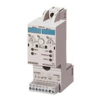
M200D PROFIBUS/PROFINET
114 Manual, 08/2014, A5E01577426A/RS-AA/004
Auxiliary voltage connection (7/8")
1 Switched 0 V (24V-S DC (-))
2 Unswitched 0 V (24V-NS DC (-))
3 —
4 Unswitched + 24 V (24V-NS DC (+))
5 Switched + 24 V (DC 24V-S (+))
Connecting M12 and 7/8" cable connectors
The current of the 7/8" connectors must not exceed 7 A!
1. Plug the M12 and 7/8" cable connectors into the corresponding circular socket
connectors on the communication module. Ensure that the locking mechanism between
the connector and socket is properly applied.
2. Secure the connectors by tightening the knurled ring nut.
It is not permissible to remove the 7/8" cable connectors while M200D PROFIBUS is in
operation! Always switch off the 24V-NS DC electronic/encoder supply and the DC 24V-S
load voltage supply before you remove or insert the 7/8" cable connector.
Removal of the 7/8" cable connector interrupts the supply to downstream modules.
Note
Sealing unused sockets
Always seal all unused sockets using M12 and 7/8" caps in order to achieve degree of
protection IP65.

 Loading...