LC700- Manual de instalação
4.9
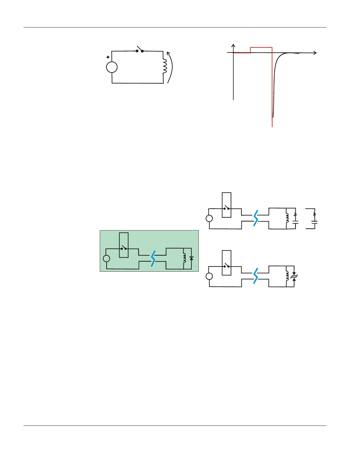
VL = L di/dt
Off
On
VL
Off
time
KV
VL
SW
L
DC
Figure 4.7 – Reverse Voltage Peak
Some alternatives may avoid this interference, like optical couplers, Zero Crossing Switching,
indirect startups that prevent the arrival of the noise to the command, but the noise generated by the
commuted device continues existing and many times it is induced in the wiring system, reaching
other automation electronic points, causing intermittent defects in the system. Therefore, those ways
of treating the noise are not effective. It should be eliminated exactly in the noise source, in other
words, in order to obtain a filter with better performance, it should be mounted the closest possible
to the commuted load.
Relay Module
L
D
AC/DC
Relay Module
Relay Module
AC/DC
L
L
R
C
R
C
RC Networ
Transil / MOV
DC
Figure 4.8 – Filters for AC and DC loads
- Inductive Load: See the specification of each LC700 I/O module related to the circuit R-C
(snubber) and to the protection diode (campling):
- Inductive DC load: In spite of the LC700 digital output modules for the DC load having a
campling diode, it is recommended to insert other campling diode close to the inductive load.
This will avoid the noise coupling in other cables that are in the same conduit