LC700 – User’s Guide
3.42
FAILURE RELAY
Output Type Solid State relay, Normally Closed (NC)
Limits 6 W, 30 Vdc max, 200 mA max.
Maximum Initial Contact Resistance <13Ω
Overload Protection Should be set externally
Operation Time 5 ms maximum
NOTE
To meet the EMC standards requirements, the wires’ length to the failure relay must be less than 30 meters.
The power supply of activated load by the failure relay must not be from external network.
OPERATION STATUS
Indicator STAND BY Green LED when it is on Stand by
DIMENSIONS AND WEIGHT
Dimensions (W x D x H)
39.9 x 137.0 x 141.5 mm;
(1.57 x 5.39 x 5.57 in)
Weight 0.410 kg
CABLES
One wire 14 AWG (2 mm
2
)
Two wires 20 AWG (0.5 mm
2
)
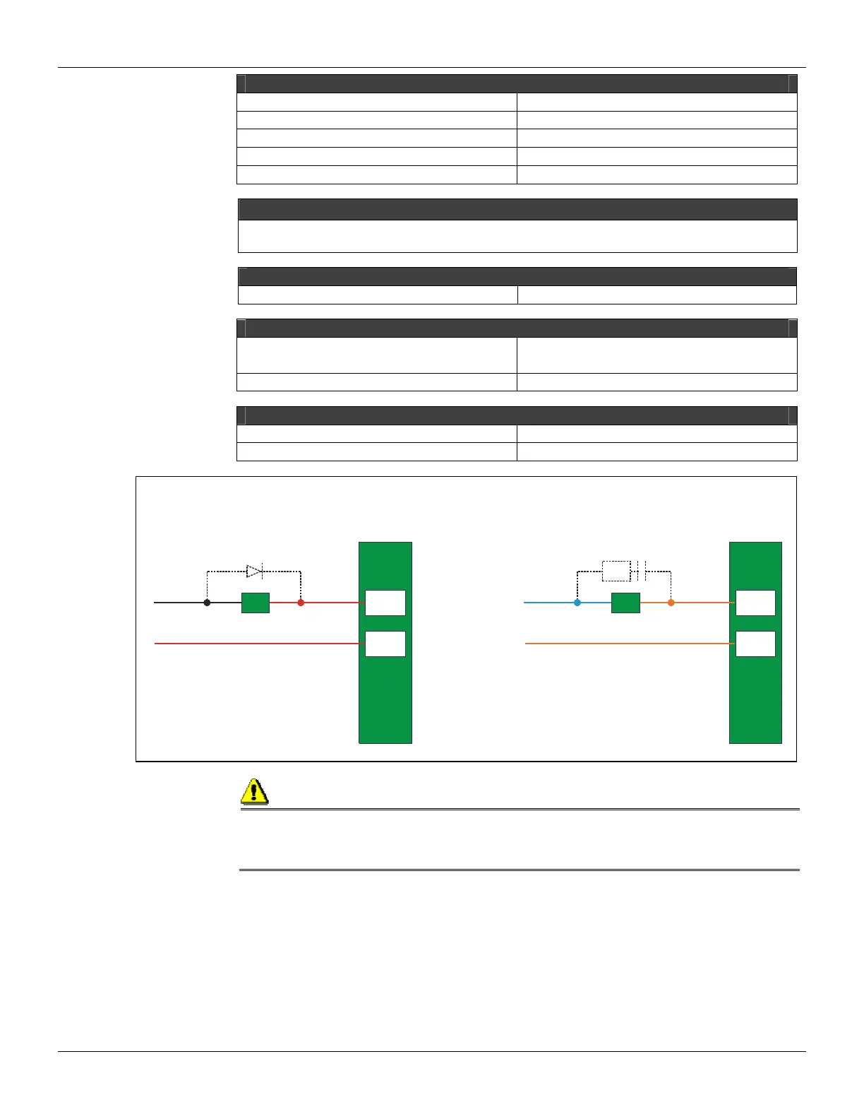
Note
To increase service of life of your relays and to protect your modules from reverse voltage damages, externally
connect a clamping diode in parallel with each inductive DC load or externally connect an RC snubber circuit in
parallel with each inductive AC load.
2 B
3 B
-
+
A
LoadD
Load
2 B
3 B
N
L
RC
Warning:
If the power consumption exceeds supplied power, the system will operate uncontrolled and
could result in damages to the device or to the user. Therefore the user must be certain to have
calculated accordingly all of the energy consumption and decide where to install more Power
Supply modules.
Energy Consumption Calculation
Once the available power of the Power Supply is limited it is necessary to calculate the power
consumed by the modules in use. One way to do this is to build a table to summarize all supplied
and necessary currents to each module and the associated equipment (such as interfaces). Next,
compute the maximum current necessary and maximum current supplied. If the maximum current
necessary is greater than the supplied current, the consumption of energy will be exceeded. If this
is the case, it will not be safe to use this configuration and the user will again have to check the
system or add more Power Supply Modules in the racks.