WSM6 Manual
Document Ref: UM-8270-000
Issue: A Rev 0
Section 8
90
6. The connection to an ammeter will not be necessary if the PSU has a built in ammeter or
output current display.
7. Re-connect the end cap to the main electronics assembly via the ribbon cable.
8. Set the current limit on the bench PSU to 100mA and voltage to 18V.
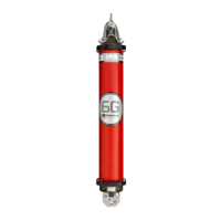
Figure 8-1 – Test configuration
1 Lower End-cap 4 Ammeter
2 Battery Connection PL1 5 Ribbon Cable Connector.
3 Power Supply Unit
October 2011