WSM6 Manual
Document Ref: UM-8270-000
Issue: A Rev 0
Section 5
October 2011 29
The WSM Terminal software, described in Section 7.3- WSM Terminal Test Software, allows the
operator
to change the scaling of the depth telemetry transmissions, but non-standard scaling must
be supported by the whole system.
The default settings are:
HPR-300 channels: 0.5 ms / m
HPR-400 channels: 1.0 ms / m (indicated as Gain = 0.3)
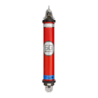
5.3.7 Location on ROV
The unit should be positioned in an upright attitude, with the transducer end-cap uppermost,
pointing towards the sea surface. If clamped to a metal structure, rubber should be used to isolate
the transponder from the structure both electrically (to prevent corrosion) and mechanically (to
damp conducted acoustic noise). Pin-out of the transponder connector is shown in Figure 3-8 –
Connector Pin numbering.
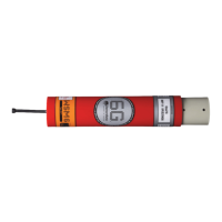
The WSM6 has a red plastic sleeve around the transponder to provide
both electrical and some
mechanical isolation.
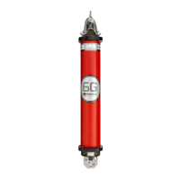
As the Type 8270 transducer has a Directional beam pattern, it can be located with the face of the
transducer flush or slightly below the level of the ROV’s syntactic foam buoyancy. This will serve to
protect the transponder in the event of accidental collisions during ROV operations.
The Type 8271 transducer has an Omni Directional beam pattern, therefore it must be located with
the transducer above the level of the ROV’s syntactic foam buoyancy.
5.3.8 Switch ON and Electrical Connections
Make sure the transponder is switched ON.
The external connector must be covered while the transponder is submerged, either by the
protective dummy plug (part no. 641-2141) or by the free plug of an external power cable (see
below).
If the unit is to operate in “Responder” mode or with external power, a 5-pin free socket with
appropriate wiring (e.g. 5m tail, Part No. 820-5163, see Figure 3-8) must be mated with the
external connector. The TRIGGER pin and COMMON must be connected via an umbilical to the
HPR or USBL system on the vessel
5.3.9 Test the Transponder
Test the transponder by interrogating with a test unit such as the Sonardyne ANT (Acoustic
Navigation Tester) as described in Section 7.10 - Programming the Acoustic Navigation Tester
(ANT). When operating with external power, also test the emergency transponder mode by
switching
off the external supply, if possible. The transponder should revert to its internal battery
supply and should continue to reply to interrogations or to electrical Responder trigger signals.
If the unit has been set up for Wideband replies, then only a suitable Wideband Interrogator can be
used to fully test the WSM6. Refer to Section 5.3.13.
NOTE
Wideband operation uses exactly the same hardware circuitry as tone operation, so if a
unit has been checked out to work on an HPR400 channel, it will have validated the
performance of the hardware.