WSM6 Manual
Document Ref: UM-8270-000
Issue: A Rev 0
ix October 2011
FIGURES
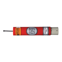
Figure 3-1 – Type 8270 Directional Wideband Sub-Mini 6G®............................................................................5
Figure 3-2 – Type 8270 Directional Wideband Sub-Mini 6G® Outline Drawing .................................................5
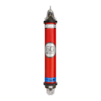
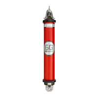
Figure 3-3 – Type 8271 Omni-Directional Wideband Sub-Mini 6G® ..................................................................6
Figure 3-4 – Type 8271 Omni Directional Wideband Sub-Mini 6G® Outline Drawing .......................................6
Figure 3-5 – Type 8270 Directional Wideband Sub-Mini 6G® End-Cap ............................................................6
Figure 3-6 – Type 8271 Omni Directional Wideband Sub-Mini 6G® End-cap....................................................7
Figure 3-7 – Connector End-cap .........................................................................................................................8
Figure 3-8 – Connector Pin numbering ...............................................................................................................9
Figure 3-9 – Type 8271-000-07 1000m rated Omni-Directional WSM6 with connector for remote Transducer
.......................................................................................................................................................................... 11
Figure 3-10 – Type 8271-000-07 – 1000M rated Omni-Directional WSM6 with straight remote Transducer . 12
Figure 3-11 – Type 8271-000-07 – 1000M Rated Omni-Directional WSM6 with right-angle remote Transducer
.......................................................................................................................................................................... 13
Figure 3-12 – Type 8065-120-XM 1000m rated straight remote Transducer .................................................. 14
Figure 3-13 – Type 8065-121-XM 1000m rated right-angle remote Transducer ............................................. 15
Figure 3-14 – Charger Connections ................................................................................................................. 18
Figure 3-15 – 8270-000-11 connector pin-out.................................................................................................. 19
Figure 3-16 – 8270-000-07 connector pin-out.................................................................................................. 20
Figure 4-1 – WSM6 Pressure Relief Vent Valve and Connector location........................................................ 21
Figure 4-2 – WSM6 ON/OFF switch................................................................................................................. 23
Figure 5-1 – Overall Acoustic Sequence HPR – 300 Series Channels ........................................................... 26
Figure 5-2 – Overall Acoustic Sequence HPR – 400 Series Channels ........................................................... 26
Figure 5-3 – HPR Responder Sequence.......................................................................................................... 27
Figure 5-4 – Connector Pin-Out and Mating Tail ............................................................................................. 32
Figure 5-5 – Mating In-line female connector (Part No. 820-5163).................................................................. 32
Figure 6-1 – Retaining Rod .............................................................................................................................. 38
Figure 6-2 – Type 8270 / 8271 Wideband Sub-Mini 6 Assembly..................................................................... 43
Figure 6-3 – Circuit Block Diagram .................................................................................................................. 44
Figure 7-1 – WSM Terminal Software Get Status ............................................................................................ 45
Figure 7-2 – Transponder connection configuration for software installation .................................................. 47
Figure 7-3 – Software operation....................................................................................................................... 48
Figure 7-4 – Serial Port Settings ...................................................................................................................... 49
Figure 7-5 – Get Status current configuration .................................................................................................. 50
Figure 7-6 – Quickset Wideband setting .......................................................................................................... 52
Figure 7-7 – Quickset Wideband Configuration ............................................................................................... 53
Figure 7-8 – Quickset Wideband® 2 setting .................................................................................................... 54
Figure 7-9 – Quickset Wideband® 2 Configuration.......................................................................................... 55
Figure 7-10 – Sonardyne Tone Setting ............................................................................................................ 56
Figure 7-11 – Mouse prompt display................................................................................................................ 57
Figure 7-12 – HPR set up................................................................................................................................. 58
Figure 7-13 – Depth Settings............................................................................................................................ 59
Figure 7-14 – Depth On/Off Settings................................................................................................................ 60
Figure 7-15 – General Settings – HPR............................................................................................................. 61
Figure 7-16 – General Settings - Address........................................................................................................ 62
Figure 7-17 – General Settings Sonardyne Interrogate ................................................................................... 63
Figure 7-18 – Download Password prompt...................................................................................................... 64
Figure 7-19 – Firmware Download ................................................................................................................... 65
Figure 7-20 – Firmware Download file selection .............................................................................................. 66
Figure 7-21 – Download settings...................................................................................................................... 67
Figure 7-22 – Firmware downloading status .................................................................................................... 68
Figure 7-23 – Firmware download complete.................................................................................................... 68
Figure 7-24 – Listening for Transponder message .......................................................................................... 70
Figure 7-25 – Listening for Transponder download ......................................................................................... 71
Figure 7-26 – Ping Test .................................................................................................................................... 72
Figure 7-27 – Channel Range Test using ANT ................................................................................................ 72
Figure 7-28 – Select Channel(s) to test............................................................................................................ 73