WSM6 Manual
Document Ref: UM-8270-000
Issue: A Rev 0
Section 3
October 2011 7
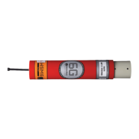
Figure 3-6 – Type 8271 Omni Directional Wideband Sub-Mini 6G® End-cap
The connector on the end-cap, is a special Subconn Micro Connector (MCBH5M Type) (Figure
3-7) and operates with a standard in-line connector MCIL5F. It allows for a responder electrical
trigger,
RS232 communications to configure the unit, a battery charging input and a separate
external dc power input.
Variations on the standard Type 8270 and 8271 are available. The Type 8270-000-07 WSM6 has a
specific 8-pin connector (refer to Section 3.5.2 - 8270-000-07 WSM6), with the pin-out compatible
with the Compatt 5 wiring; the Type 8270-000-11 WSM6 (refer to Section 3.5.1 - 8270-000-11
WSM6) has a specific 5-pin female connector.
A
standard Subconn non-shorting blanking plug should be fitted when deployed if the connector on
the unit is not being used.
Unless the unit is damaged or fails to function correctly after charging, there is no requirement to
open the pressure housing. If access to the electronics or battery is required, this must be carried
out by qualified maintenance personnel.
The WSM6 is designed to be operated in both transponder and responder modes. An electrical
trigger input pin is provided on the external connector to enable operation in responder mode.
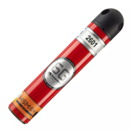
The main housing label contains the unit serial number which should be quoted in all
correspondence with Sonardyne.
The acoustic command address and the interrogation channel are given on a separate housing
label. These can be changed by software, via the RS232 link.
All HPR-300 channels, 01 to 09 plus 11, 22, 33, 44 and 55, are available, as well as all the HPR-
400 channels. All Sonardyne navigation channels are also supported including the new wideband
reply signals. A full table of frequencies for each valid navigation channel is given in Appendix B -
Frequency Tables.
Acoustic commands are available to enable and disable the
transponder and to switch on the depth
reply.