WSM6 Manual
Document Ref: UM-8270-000
Issue: A Rev 0
Section 8
100
8.5.1.8 Responder Mode
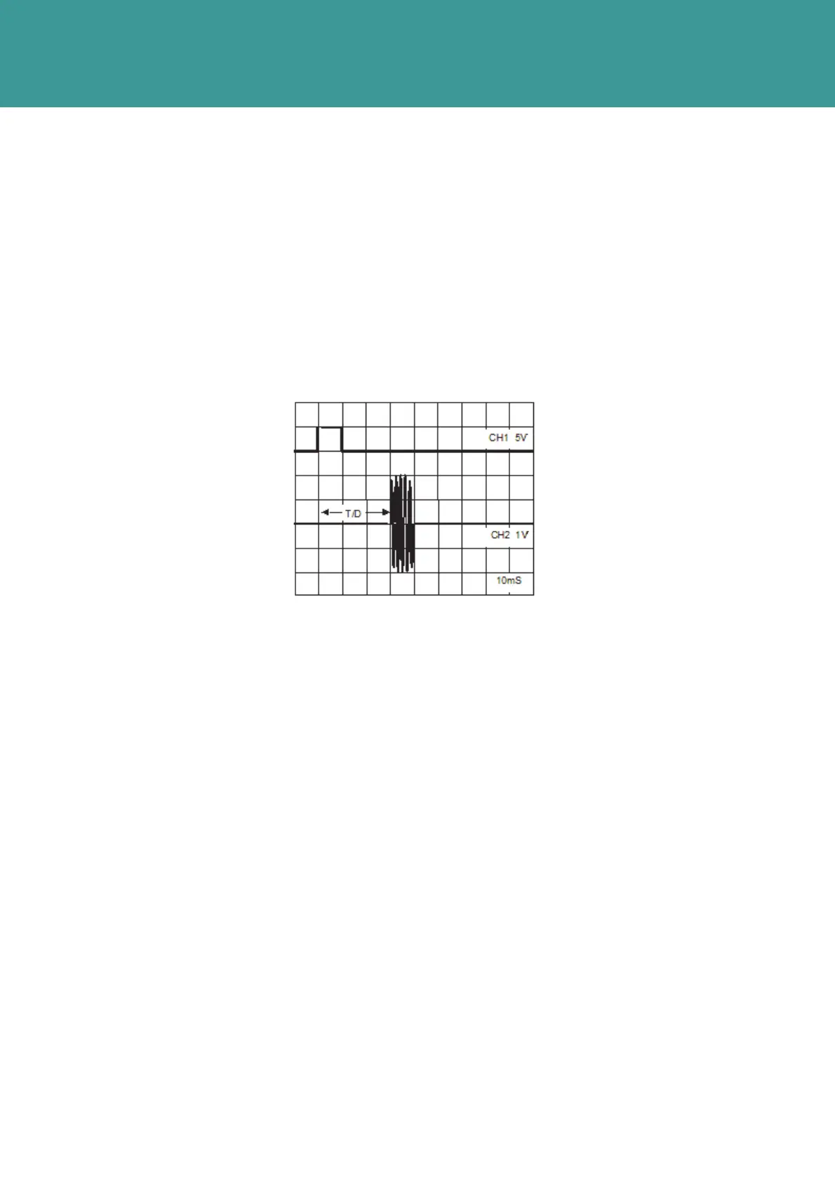
1. Use Test Cable 1 to apply a +ve going pulse to the Pin 1 (black wire), wrt 0V (white wire), 5V
amplitude, with a duration of 10ms and a repetition rate of 750ms. Refer to Figure 8-12.
2.
The 10ms trigger waveform and a normal output waveform should be present.
3. If the output waveform is not present, the upper board is faulty.
4. If the waveform is present, repeat the test for the full range of channel selection switch
settings.
Figure 8-12 – O/P from Coupling Loop
October 2011