WSM6 Manual
Document Ref: UM-8270-000
Issue: A Rev 0
Section 5
32
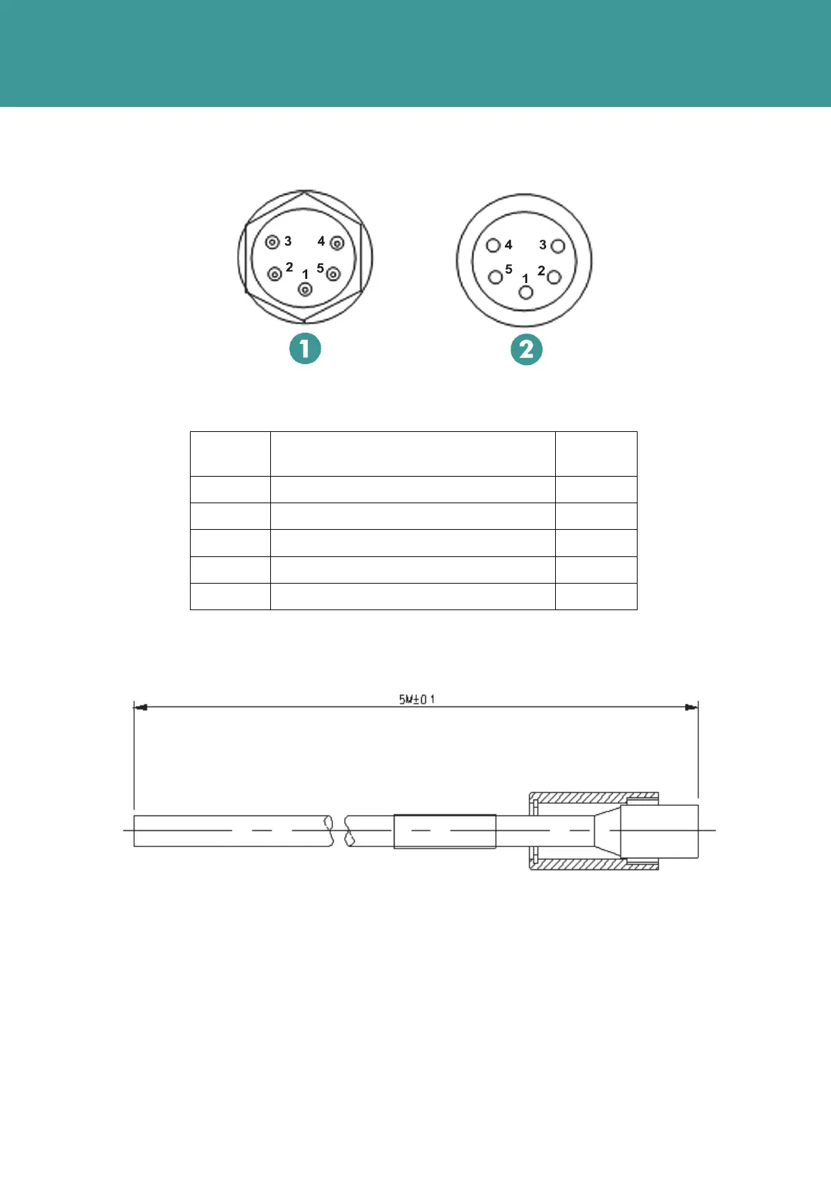
Figure 5-4 – Connector Pin-Out and Mating Tail
1 Bulkhead male 2 Cable female
Pin
number
Function Colour
1 Trigger In / Comms In Black
2 0V White
3 Fast Charge / Comms out Red
4 External Power 24V and trickle charge Green
5 Not used Orange
Figure 5-5 – Mating In-line female connector (Part No. 820-5163)
Refer to Section 3.5.1– 8270-000-11 WSM6, and Section 3.5.2 – 8270-000-07 WSM6 for wiring
configurations for variant transponders.
October 2011