WSM6 Manual
Document Ref: UM-8270-000
Issue: A Rev 0
Section 8
93
8.4.1.4 100kHz Oscillator
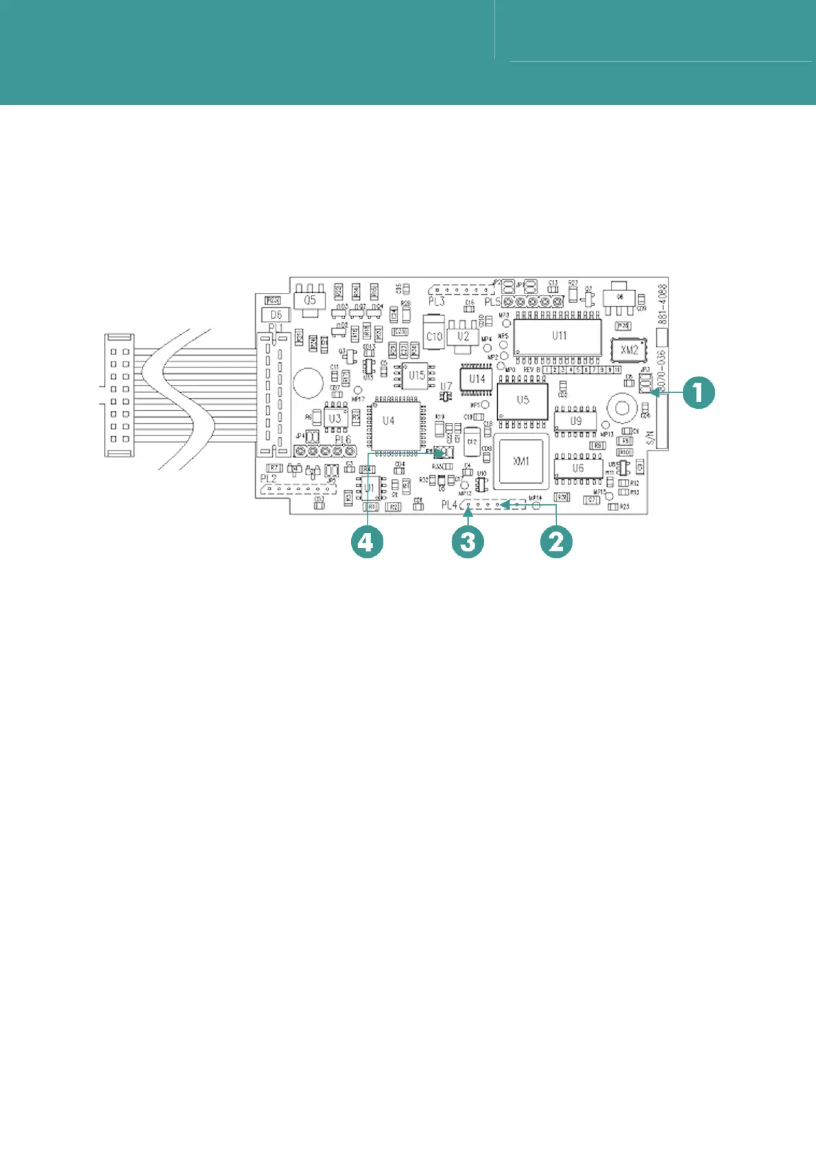
1. Use a x10 probe and frequency counter, check a 5V 100kHz square wave is present on the
middle pad of JP8. Refer to Figure 8-3.
Figure 8-3 – CPU Board 8270-036
1JP3.3 3PL4.1
2PL4.4 4JP8.2
8.4.1.5 CPU Operation
1. Connect a PC using the charger/comms interface.
2. Run WSM Terminal Software.
3. Switch the WSM6 ON.
4. Select Get Status on the software main page.
5. Check the transponder returns data by populating the boxes on the screen.
6. This proves the operation of the micro-controller and associated crystal.
8.4.1.6 24V Input Test
1. Using test Cable 1 (MCIL5F) connect the +24V (pin 4 – red wire) to the PSU +ve output, and
the 0V (pin 2 – black wire) to the PSU –ve output.
2. Set the PSU voltage to 24V.
3. Check the voltage on C16. This should be approximately 23.4V and the circuit should be
drawing a current of approximately 85mA.
October 2011