WSM6 Manual
Document Ref: UM-8270-000
Issue: A Rev 0
Section 8
98
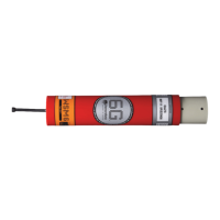
8.5.1.4 IIFDET and TXPW Output
1. These waveforms are monitored on PL4-1 and PL4-4 on the upper board. Refer to Figure
8-8.
2.
The time between the falling edge of IIFDET and the 2
nd
falling edge of TXPW should be
39.2ms ±200µs.
3. If the times are incorrect then the upper board is faulty.
4. There is a possibility the lower board or PL4 is faulty, change the upper board for the lower
board and observer the result.
Figure 8-8 – IIFDET and TXPW Waveform
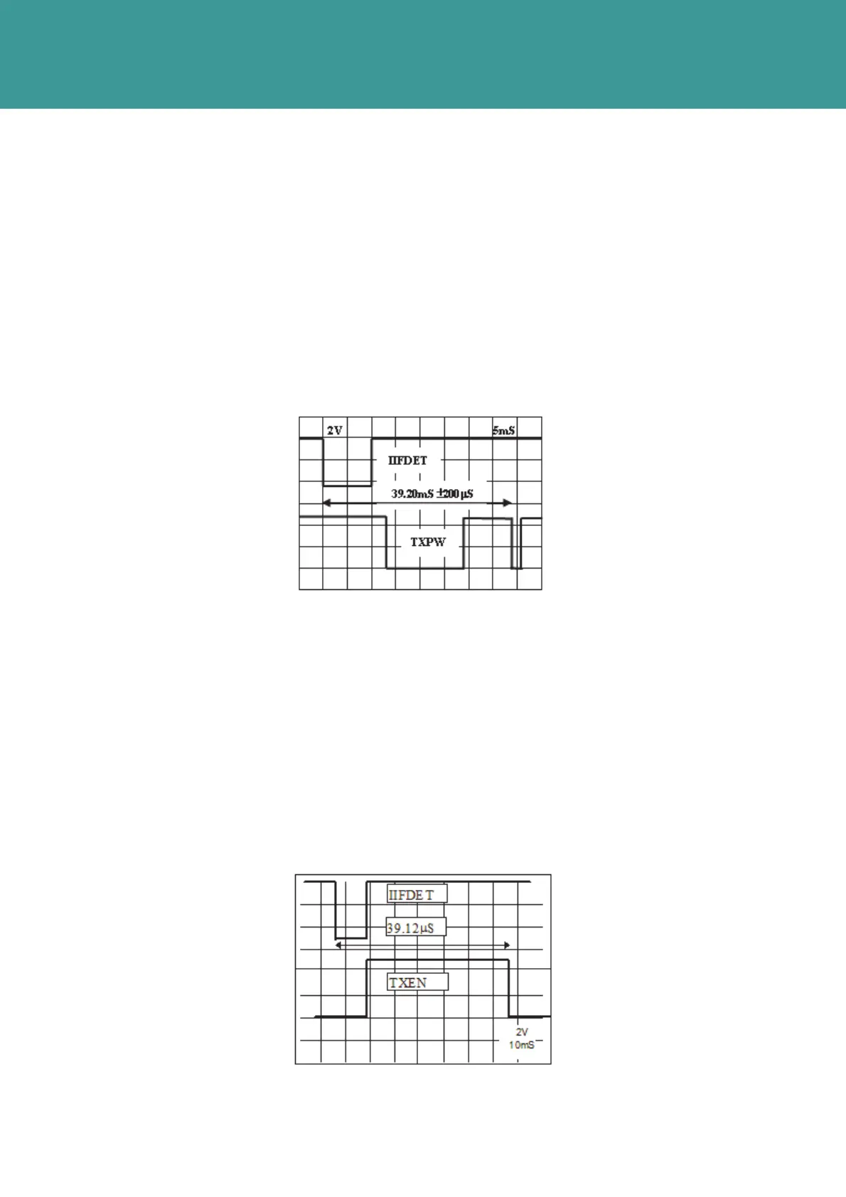
8.5.1.5 IIFDET and TXEN Output
1. This waveform is monitored on PL4-1 and PL4-5 on the upper board respectively. Refer to
Figure 8-9.
2.
The time between the falling edge of IIFDET and the falling edge of TXEN should be 39.12ms
± 200µs.
3. If the waveform does not resemble that shown in Figure 8-9, then the upper board is faulty.
4.
It is possible for the lower board or PL2 (or mating connector) to be faulty. To determine this
change the lower board and observe the results.
Figure 8-9 – IIFDET and TXEN Waveform
October 2011