WSM6 Manual
Document Ref: UM-8270-000
Issue: A Rev 0
Section 8
99
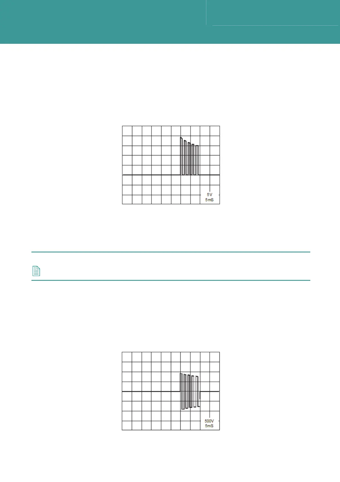
8.5.1.6 Drive Amplifier Input
1. This waveform is monitored on the Gates of U17 pin 4 and U18 pin 4 on the lower Tx board.
Refer to Figure 8-10.
2.
If it does not appear as shown in Figure 8-10, then the Tx board is faulty.
Figure 8-10 – Drive Amp I/P Waveform
8.5.1.7 Drive Amplifier O/P Output
1. This waveform is monitored using the x100 probe on PL3 pin 1 on the lower board. Refer to
Figure 8-11.
NOTE
The voltage is very high at this point – 1800V p/p.
2. If the waveform is not as shown in Figure 8-11, then the lower board is faulty.
3. If the waveform is present it should be possible to hear the transducer “pinging” as it
produces the reply burst.
4. If there is no sign of transducer output, then the transducer is faulty.
Figure 8-11 – Drive Amp O/P Waveform
October 2011