WSM6 Manual
Document Ref: UM-8270-000
Issue: A Rev 0
Section 8
97
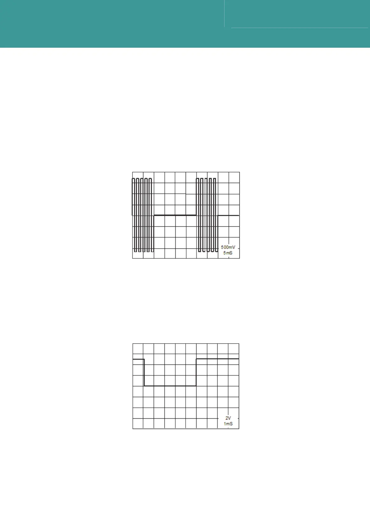
8.5.1.2 Squarer Stage Output
1. This waveform is monitored at TP3 on the lower board. Refer to Figure 8-6.
2.
Both input and reply signals should appear. The input starts at 0ms, and the reply starts at
approximately 30ms.
3. Both signals should reach saturation level at the amplifier output – an amplitude of 5.0V p/p.
4. If the input signal is not present, U13, U11 or U19 is faulty.
Figure 8-6 – Pre-Amp 2
nd
Stage Waveform
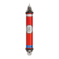
8.5.1.3 Envelope Detector Output
1. This waveform is monitored at TP4 on the lower board. Refer to Figure 8-7.
2.
If the waveform does not appear as shown, and assuming the CPU board was found to be
working correctly, the lower board is faulty.
Figure 8-7 – Comparator O/P Waveform
October 2011