WSM6 Manual
Document Ref: UM-8270-000
Issue: A Rev 0
Section 6
42 October 2011
7. Fit a fresh silica gel bag.
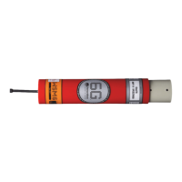
8. Insert the transducer / chassis assembly into the housing.
9. Make sure the transducer end-cap and housing are assembled correctly and insert the
flexible plastic retaining rod to secure.
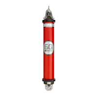
10. Screw the pin on the end of the nylon retaining cord to the stud on the connector end-cap,
forming the second locating pin.
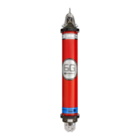
11. Connect the ribbon cable to the connector end-cap PCB.
12. Position the connector end-cap to the housing and align the notches in the end-cap with the
housing. As the end-cap is inserted into the housing, the ribbon cable should fold down neatly
without needing any special action.
13. Insert the flexible plastic retaining rod to secure the connector end-cap to the housing.
14. Unless the battery is to charged immediately, remove the protective tape from the Pressure
Relief Vent Valve.
15. Clean the lightly lubricate the ‘O’-rings.
16. Make sure the Pressure Relief Vent Valve seats flush with the connector end-cap.
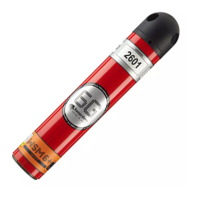
17. Fit the red plastic sleeve over the whole unit.
18. Make sure the connectors are lubricated, refer to Section
6.6 - Lubrication
19.
Carry out a functional test, refer to Section 7 – WSM6 Functional Test.