DocID018909 Rev 11 129/1731
RM0090 Power controller (PWR)
149
Peripheral clock gating is controlled by the AHB1 peripheral clock enable register
(RCC_AHB1ENR), AHB2 peripheral clock enable register (RCC_AHB2ENR), AHB3
peripheral clock enable register (RCC_AHB3ENR) (see Section 7.3.10: RCC AHB1
peripheral clock enable register (RCC_AHB1ENR), Section 7.3.11: RCC AHB2 peripheral
clock enable register (RCC_AHB2ENR), Section 7.3.12: RCC AHB3 peripheral clock
enable register (RCC_AHB3ENR) for STM32F405xx/07xx and STM32F415xx/17xx, and
Section 6.3.10: RCC AHB1 peripheral clock register (RCC_AHB1ENR), Section 6.3.11:
RCC AHB2 peripheral clock enable register (RCC_AHB2ENR), and Section 6.3.12: RCC
AHB3 peripheral clock enable register (RCC_AHB3ENR) for STM32F42xxx and
STM32F43xxx).
Disabling the peripherals clocks in Sleep mode can be performed automatically by resetting
the corresponding bit in RCC_AHBxLPENR and RCC_APBxLPENR registers.
5.3.3 Sleep mode
Entering Sleep mode
The Sleep mode is entered according to Section : Entering low-power mode, when the
SLEEPDEEP bit in the Cortex
®
-M4 with FPU System Control register is cleared.
Refer to Table 24 and Table 25 for details on how to enter Sleep mode.
Note: All interrupt pending bits must be cleared before the sleep mode entry.
Exiting Sleep mode
The Sleep mode is exited according to Section : Exiting low-power mode.
Refer to Table 24 and Table 25 for more details on how to exit Sleep mode.
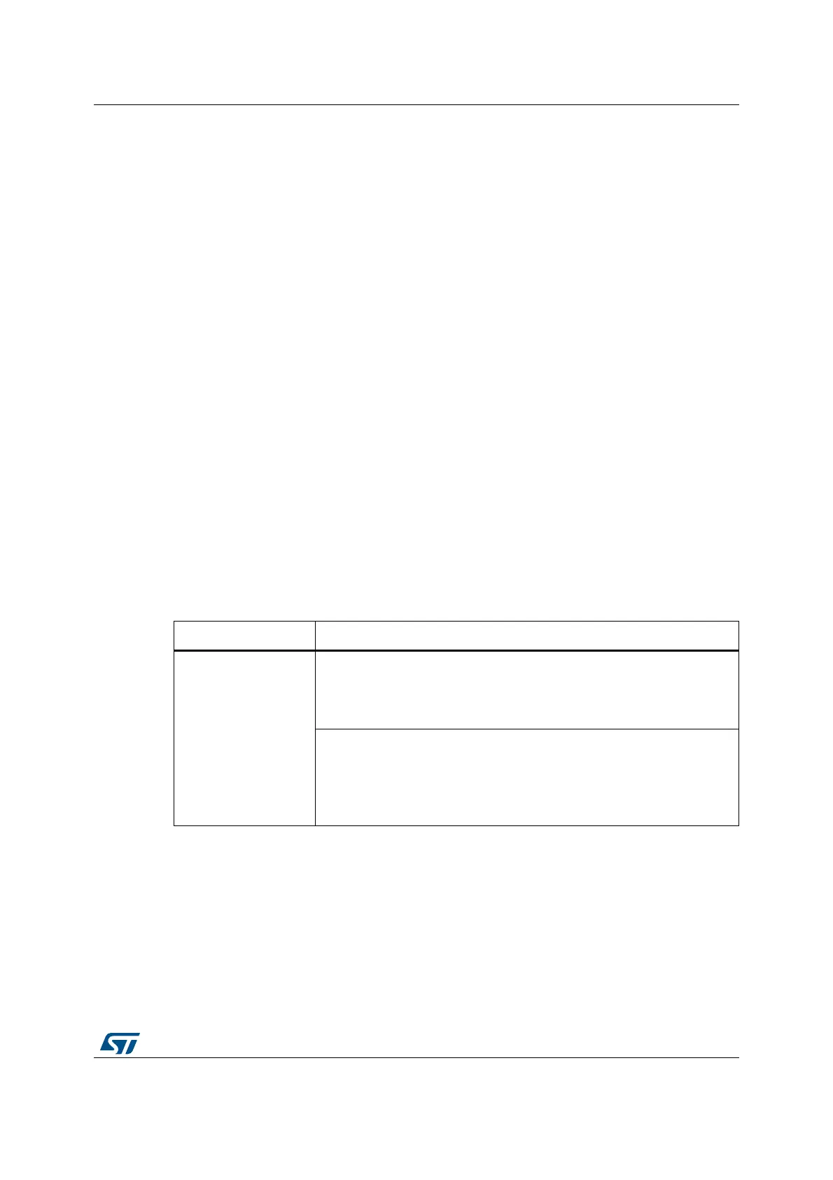
Table 24. Sleep-now entry and exit
Sleep-now mode Description
Mode entry
WFI (Wait for Interrupt) or WFE (Wait for Event) while:
– SLEEPDEEP = 0, and
– No interrupt (for WFI) or event (for WFE) is pending.
Refer to the Cortex
®
-M4 with FPU System Control register.
On Return from ISR while:
– SLEEPDEEP = 0 and
– SLEEPONEXIT = 1,
– No interrupt is pending.
Refer to the Cortex
®
-M4 with FPU System Control register.