DocID018909 Rev 11 363/1731
RM0090 Chrom-Art Accelerator™ controller (DMA2D)
372
11.5.10 DMA2D background PFC control register (DMA2D_BGPFCCR)
Address offset: 0x0024
Reset value: 0x0000 0000
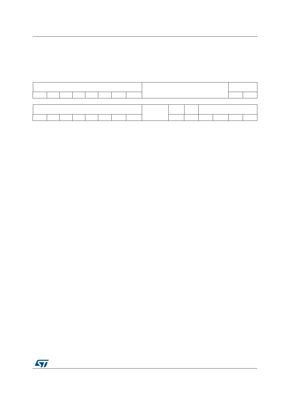
31 30 29 28 27 26 25 24 23 22 21 20 19 18 17 16
ALPHA[7:0]
Reserved
AM[1:0]
rw rw rw rw rw rw rw rw rw rw
15 14 13 12 11 10 9 8 7 6 5 4 3 2 1 0
CS[7:0]
Reserved
START CCM CM[3:0]
rw rw rw rw rw rw rw rw rc_w1 rw rw rw rw rw
Bits 31:24 ALPHA[7: 0]: Alpha value
These bits define a fixed alpha channel value which can replace the original alpha value
or be multiplied with the original alpha value according to the alpha mode selected with
bits AM[1: 0]. These bits can only be written when data transfers are disabled. Once the
transfer has started, they are read-only.
Bits 23:18 Reserved, must be kept at reset value
Bits 17:16 AM[1: 0]: Alpha mode
These bits define which alpha channel value to be used for the background image.
These bits can only be written when data transfers are disabled. Once the transfer has
started, they are read-only.
00: No modification of the foreground image alpha channel value
01: Replace original background image alpha channel value by ALPHA[7: 0]
10: Replace original background image alpha channel value by ALPHA[7:0] multiplied
with original alpha channel value
others: meaningless
Bits 15:8 CS[7: 0]: CLUT size
These bits define the size of the CLUT used for the BG. Once the CLUT transfer has
started, this field is read-only.
The number of CLUT entries is equal to CS[7:0] + 1.
Bits 7:6 Reserved, must be kept at reset value