EasyManua.ls Logo

STMicroelectronics STM32F407 User Manual

STMicroelectronics STM32F407
1731 pages
To Next Page IconTo Next Page
To Previous Page IconTo Previous Page
Page #692 background image
Basic timers (TIM6&TIM7) RM0090
692/1731 DocID018909 Rev 11
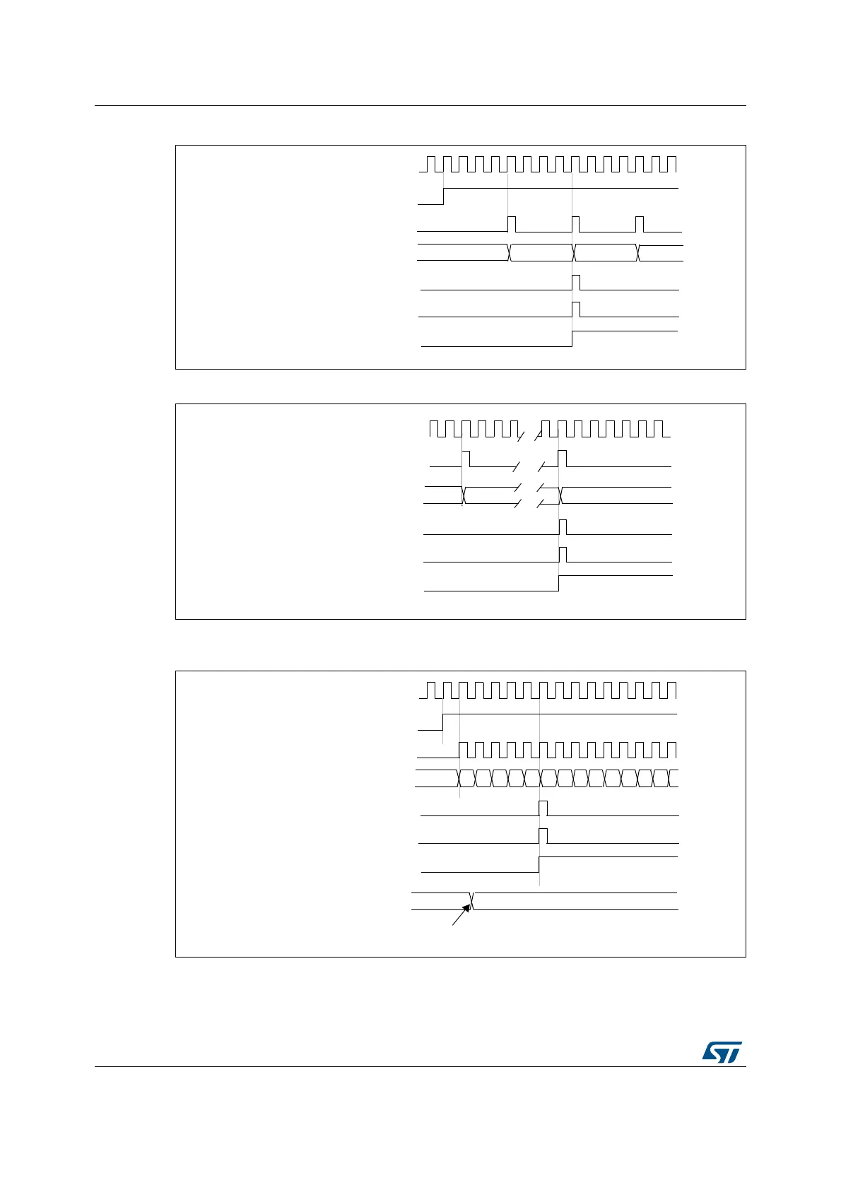
Figure 208. Counter timing diagram, internal clock divided by 4
Figure 209. Counter timing diagram, internal clock divided by N
Figure 210. Counter timing diagram, update event when ARPE = 0 (TIMx_ARR not
preloaded)
0000 0001
CNT_EN
TImer clock = CK_CNT
Counter register
Update interrupt flag (UIF)
0035
0036
Counter overflow
Update event (UEV)
CK_INT
Timer clock = CK_CNT
Counter register
00
1F
20
Update interrupt flag (UIF)
Counter overflow
Update event (UEV)
CK_INT
00
CNT_EN
Timer clock = CK_CNT
Counter register
Update interrupt flag (UIF)
Counter overflow
Update event (UEV)
01 02 03 04 05 06 0732 33 34 35 3631
Auto-reload register
FF 36
Write a new value in TIMx_ARR
CK_INT

Table of Contents

Question and Answer IconNeed help?

Do you have a question about the STMicroelectronics STM32F407 and is the answer not in the manual?

STMicroelectronics STM32F407 Specifications

General IconGeneral
SeriesSTM32F4
CoreARM Cortex-M4
Max Clock Speed168 MHz
Flash MemoryUp to 1 MB
SRAMUp to 192 KB
ADC Resolution12-bit
DAC Channels2
DAC Resolution12-bit
I2CUp to 3
SPI3
Timers17
USBUSB
Communication InterfacesUSB, I2C, SPI
Operating Supply Voltage1.8 V to 3.6 V
Operating Temperature-40°C to +85°C
PackageLQFP100, LQFP64

Related product manuals