DocID018909 Rev 11 395/1731
RM0090 Analog-to-digital converter (ADC)
434
13.3.5 Continuous conversion mode
In continuous conversion mode, the ADC starts a new conversion as soon as it finishes one.
This mode is started with the CONT bit at 1 either by external trigger or by setting the
SWSTRT bit in the ADC_CR2 register (for regular channels only).
After each conversion:
• If a regular group of channels was converted:
– The last converted data are stored into the 16-bit ADC_DR register
– The EOC (end of conversion) flag is set
– An interrupt is generated if the EOCIE bit is set
Note: Injected channels cannot be converted continuously. The only exception is when an injected
channel is configured to be converted automatically after regular channels in continuous
mode (using JAUTO bit), refer to Auto-injection section)
.
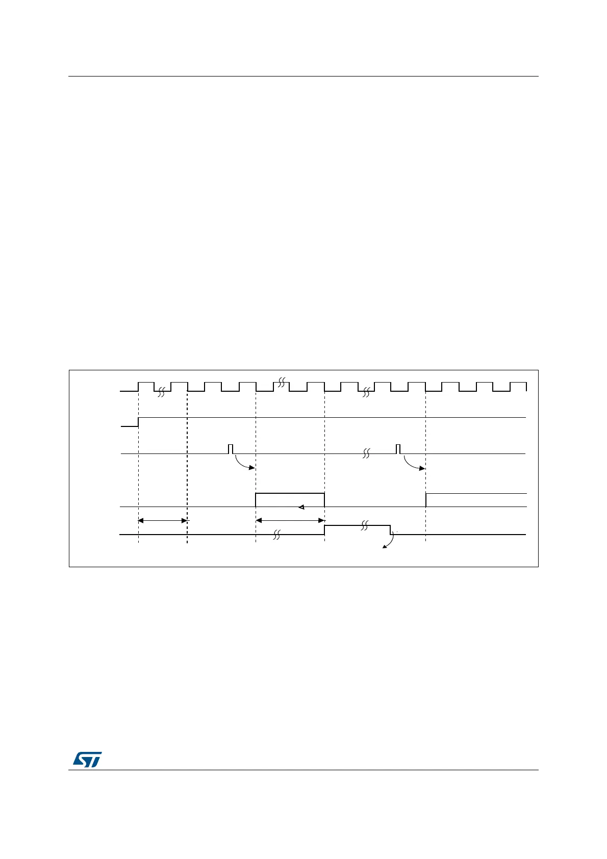
13.3.6 Timing diagram
As shown in Figure 45, the ADC needs a stabilization time of t
STAB
before it starts
converting accurately. After the start of the ADC conversion and after 15 clock cycles, the
EOC flag is set and the 16-bit ADC data register contains the result of the conversion.
Figure 45. Timing diagram
13.3.7 Analog watchdog
The AWD analog watchdog status bit is set if the analog voltage converted by the ADC is
below a lower threshold or above a higher threshold. These thresholds are programmed in
the 12 least significant bits of the ADC_HTR and ADC_LTR 16-bit registers. An interrupt can
be enabled by using the AWDIE bit in the ADC_CR1 register.
The threshold value is independent of the alignment selected by the ALIGN bit in the
ADC_CR2 register. The analog voltage is compared to the lower and higher thresholds
before alignment.
Table 66 shows how the ADC_CR1 register should be configured to enable the analog
watchdog on one or more channels.
!$#?#,+
%/#
.EXT!$#CONVERSION
!$#CONVERSION
#ONVERSIONTIME
T
34!"
!$#
3OFTWARECLEARSTHE%/#BIT
TOTALCONVTIME
3TARTSTCONVERSION 3TARTNEXTCONVERSION
AIB
!$/.
3734!24
*3734!24