DocID018909 Rev 11 91/1731
RM0090 Embedded Flash memory interface
112
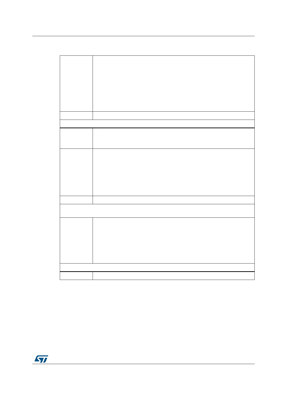
Bits 3:2
BOR_LEV: BOR reset Level
These bits contain the supply level threshold that activates/releases the reset.
They can be written to program a new BOR level value into Flash memory.
00: BOR Level 3 (VBOR3), brownout threshold level 3
01: BOR Level 2 (VBOR2), brownout threshold level 2
10: BOR Level 1 (VBOR1), brownout threshold level 1
11: BOR off, POR/PDR reset threshold level is applied
Note: For full details on BOR characteristics, refer to the “Electrical
characteristics” section of the product datasheet.
Bits 1:0 0x1: Not used
Option bytes (word, address 0x1FFF C008)
Bit 15
SPRMOD: Selection of protection mode of nWPRi bits
0: nWPRi bits used for sector i write protection (Default)
1: nWPRi bits used for sector i PCROP protection (Sector)
Bit 14
DB1M: Dual bank 1 Mbyte Flash memory devices
0: 1 Mbyte single Flash memory (contiguous addresses in bank 1)
1: 1 Mbyte dual bank Flash memory. The Flash memory is organized as two banks
of 512 Kbytes each (see Table 7: 1 Mbyte Flash memory single bank vs dual bank
organization (STM32F42xxx and STM32F43xxx) and Table 9: 1 Mbyte dual bank
Flash memory organization (STM32F42xxx and STM32F43xxx)). To perform an
erase operation, the right sector must be programmed (see Table 7 for information
on the sector numbering scheme).
Bits 13:12 0x2: not used
nWRP: Flash memory write protection option bytes for bank 1. Sectors 0 to 11 can be write
protected.
Bits 11:0
nWRPi:
If SPRMOD is reset (default value):
0: Write protection active on sector i.
1: Write protection not active on sector i.
If SPRMOD is set (active):
0: PCROP protection not active on sector i.
1: PCROP protection active on sector i.
Option bytes (word, address 0x1FFE C000)
Bit 15:0 0xFFFF: not used
Table 16. Description of the option bytes
(STM32F42xxx and STM32F43xxx) (continued)