STOBER 8 | Connection
12/2018 | ID 442537.05
101
8.5.3 PN6 – PROFINET
For a PROFINET connection, you need the optional PN6 accessory part.
8.5.3.1 Overview
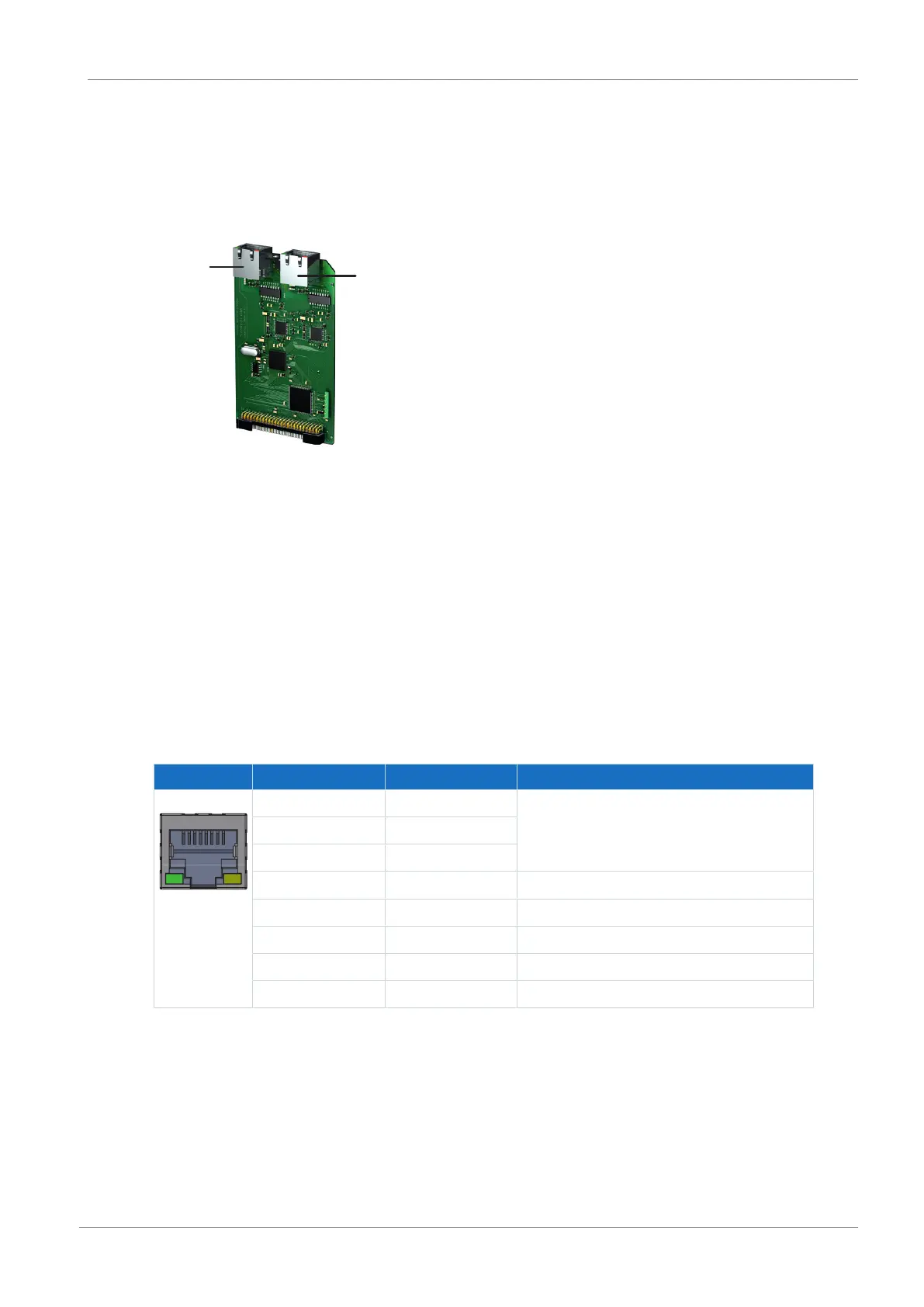
Fig.20: Connection overview for PN6 communication module
1 X200: PROFINET
2 X201: PROFINET
8.5.3.2 X200, X201: PROFINET
In order to be able to connect the drive controllers to other PROFINET nodes, an integrated
switch with both X200 and X201 RJ-45 sockets is provided. The sockets are located on top of
the device. The associated pin assignment and color coding correspond to the EIA/TIA-T568B
standard.
Connect X200 or X201 with the IO controller and the remaining connection with the next drive
controller.
Socket Pin Designation Function
1|2| ... |7|8 1 Tx+ Communication
2 Tx−
3 Rx+
4 — —
5 — —
6 Rx− Communication
7 — —
8 — —
Tab. 98: X200 and X201 connection description
Cable requirements
A PROFINET network generally consists of symmetrical, shielded copper cables twisted in pairs
(shielded twisted pair, CAT 5e quality level).
Signals are transmitted according to the 100BASE TX method, i.e. with a transfer rate of
100Mbps at a frequency of 125MHz.
A maximum of 1440bytes can be transferred per frame. The maximum cable length is 100m.

 Loading...

