8 | Connection STOBER
82
12/2018 | ID 442537.05
8.4.8 X6: Brake – Feedback and supply (ST6 option)
X6 is used for brake diagnostics and supply. The X6 connection is part of the ST6 safety
module.
Electrical data All types
U
1
24 V
DC
, +25%
I
1max
6A, UL: 4A
Tab. 63: Electrical data for the brake supply
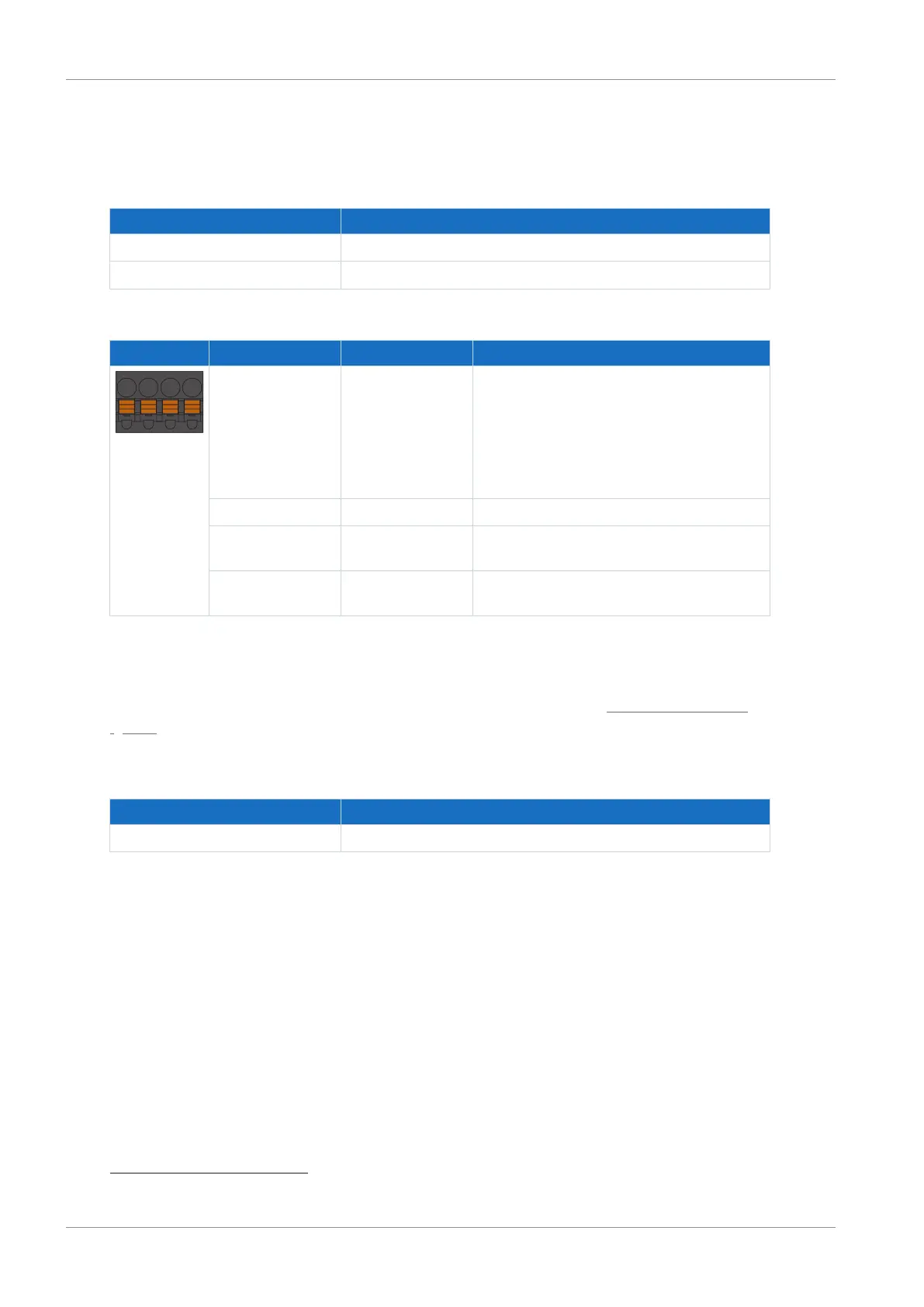
Terminal Pin Designation Function
1 | 2 | 3 | 4
1 Feedback Feedback input of an optional switching
amplifier for braking diagnostics; if the brake
is connected to SD6 indirectly (e.g. via a
coupling contactor) and the switching
amplifier is to be monitored, pins 1 and 2
must be connected via an external N/O
contact
2 GND Reference potential for feedback
3 + 24V
DC
supply for the brake; recommended
fuse protection: max. 6AT
6
4 − Reference potential for supply voltage of the
brake
Tab. 64: X6 connection description
Connecting wiring
For connecting wiring, observe the terminal specifications in the chapter BFL 5.08HC 180 SN
[}153].
Cable requirements
Feature All sizes
Max. cable length 30m
Tab. 65: Cable length [m]
6
For UL-compliance, use of a 4A fuse (time delay) is required. Be sure that the fuse meets certification re-
quirements for DC voltage in accordance with UL 248.

 Loading...

