8 | Connection STOBER
90
12/2018 | ID 442537.05
8.4.16 X20: Motor
The motor is connected to X20. For size 3 device types, there is also the connection for the DC
link connection and for a braking resistor at terminal X20.
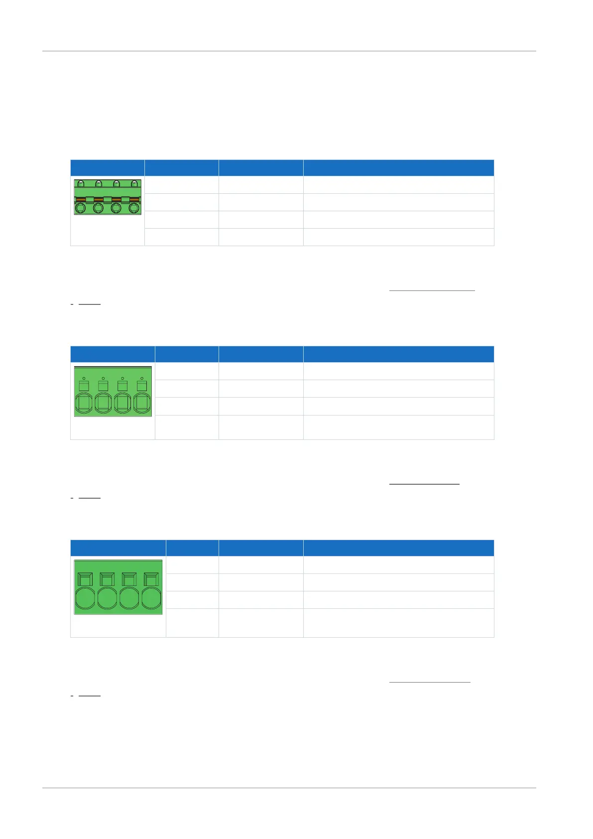
Size 0
Terminal Pin Designation Function
1 | 2 | 3 | 4
1 U Phase U motor connection
2 V Phase V motor connection
3 W Phase W motor connection
4 PE Grounding conductor
Tab. 85: X20 connection description – Size 0
For connecting wiring, observe the terminal specifications in the chapter GFKC 2,5 -ST-7,62
[}154].
Size 1
Terminal Pin Designation Function
1 | 2 | 3 | 4
1 U Phase U motor connection
2 V Phase V motor connection
3 W Phase W motor connection
4 PE Grounding conductor
Tab. 86: X20 connection description – Size 1
For connecting wiring, observe the terminal specifications in the chapter SPC 5 -ST-7,62
[}155].
Size 2
Terminal Pin Designation Function
1 | 2 | 3 | 4
1 U Phase U motor connection
2 V Phase V motor connection
3 W Phase W motor connection
4 PE Grounding conductor
Tab. 87: X20 connection description – Size 2
For connecting wiring, observe the terminal specifications in the chapter SPC 16 -ST-10,16
[}156].

 Loading...


