5 | Technical data STOBER
34
12/2018 | ID 442537.05
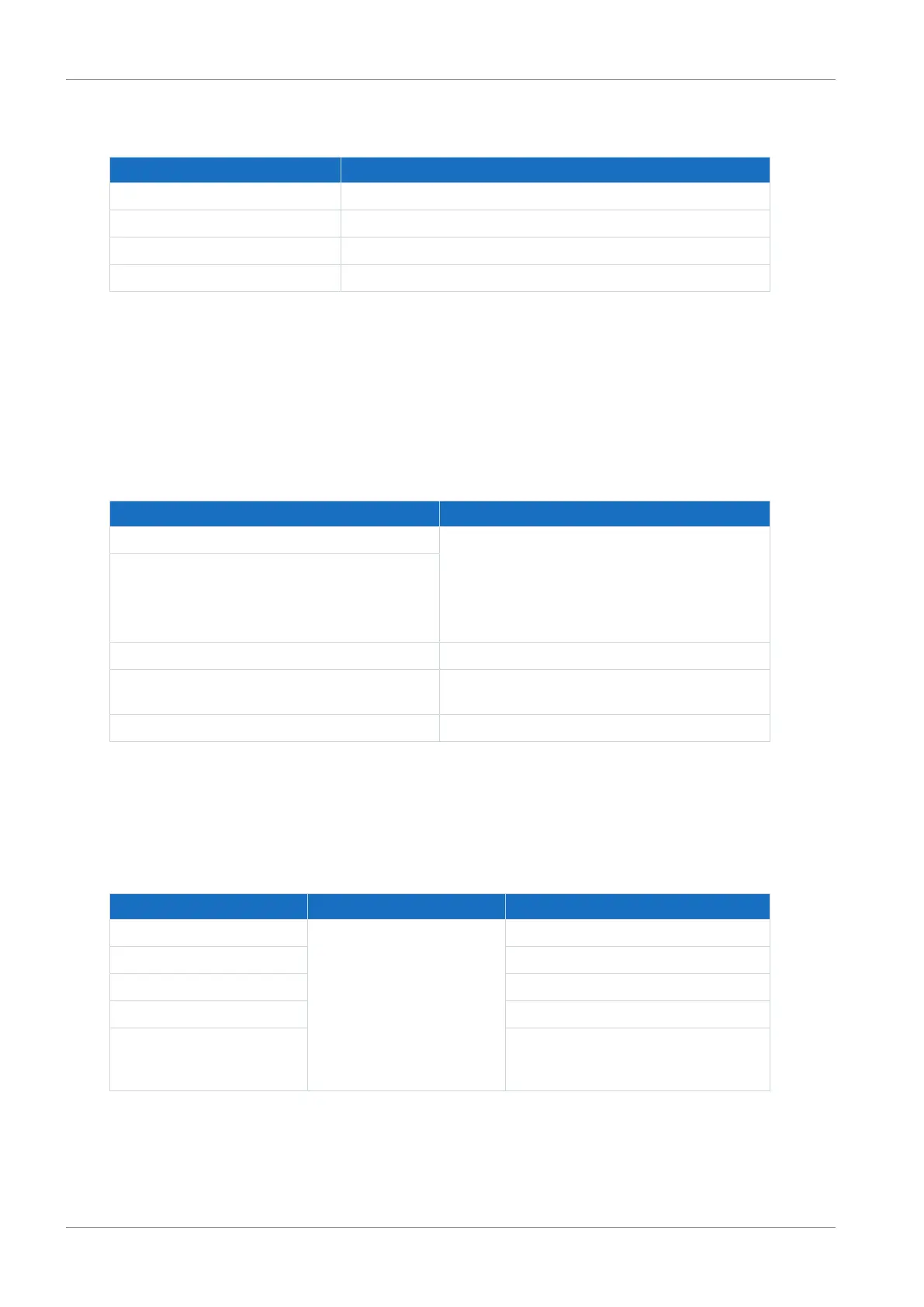
5.2.4 Weight
Type Weight without packaging [g]
DL6A0 500
DL6A1 510
DL6A2 660
DL6A3 800
Tab. 38: DL6A weight [g]
5.3 Safety technology
5.3.1 ST6
The ST6 safety module adds the STO safety function to the SD6 drive controller via terminal
X12.
Specification Electrical data
STO
a
U
1max
= 30V
DC
(PELV)
high level = 15 – 30V
DC
low level = 0 – 8V
DC
I
1max
= 100mA (typically < 30mA for 24V
DC
)
I
max
= 4A
C
1max
= 100nF
STO
b
STO
status
U
2
= U
1
− (200mΩ * I
1
)
STO
status
supply U
1
= +24V
DC
, +20%/25%
I
1max
= 100mA
GND —
Tab. 39: X12 electrical data (ST6 option)
5.3.2 SE6
The SE6 safety module adds the expanded safety functions to the SD6 drive controllers using
terminals X14 and X15.
Electrical data Digital input Value
Low level I0–I7 −3 – +5V
DC
High level 15 – 30V
DC
U
1max
30V
DC
I
1max
10.8mA
f
1max
<250Hz; results from the SE6 cycle
time and the configurable filter time
constant of the input
Tab. 40: X14 electrical data – Digital inputs (SE6 option)

 Loading...

