11 | Diagnostics STOBER
138
12/2018 | ID 442537.05
11 Diagnostics
LEDs on the top and front give you initial information about the device state of the respective
device as well as the states of the physical connection and the communication. In the event of
an error or fault, you will receive detailed information through the DriveControlSuite
commissioning software.
11.1 Drive controllers
STOBER drive controllers have diagnostic LEDs that visually indicate the state of the drive
controller as well as the states of the physical connection and communication.
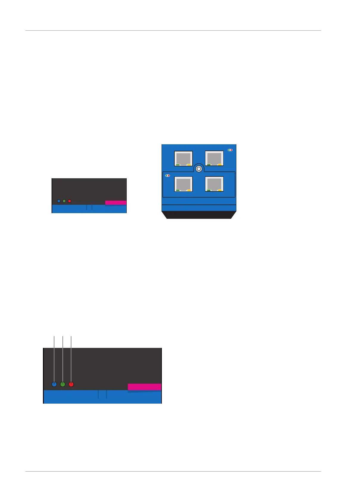
Fig.27: Positions of the diagnostic LEDs on the front and top of the drive controller
1 Drive controller state
2 Service network connection
3 Fieldbus state
4 IGB state
5 Fieldbus network connection
11.1.1 Drive controller state
3 LEDs on the front of the device provide information about the state of the drive controller.
Fig.28: LEDs for the state of the drive controller on the front of the SD6
1 Blue: REMOTE
2 Green: RUN
3 Red: ERROR

 Loading...


