STOBER 8 | Connection
12/2018 | ID 442537.05
79
8.4.6 X4: Encoder
The encoders described below can be connected to X4.
ATTENTION!
Risk of encoder destruction!
X4 may not be plugged in or unplugged when the device is switched on!
Evaluable encoders
The technical data of the evaluable encoders at X4 can be found in the manual for the SD6
drive controller; see the chapter Detailed information [}161].
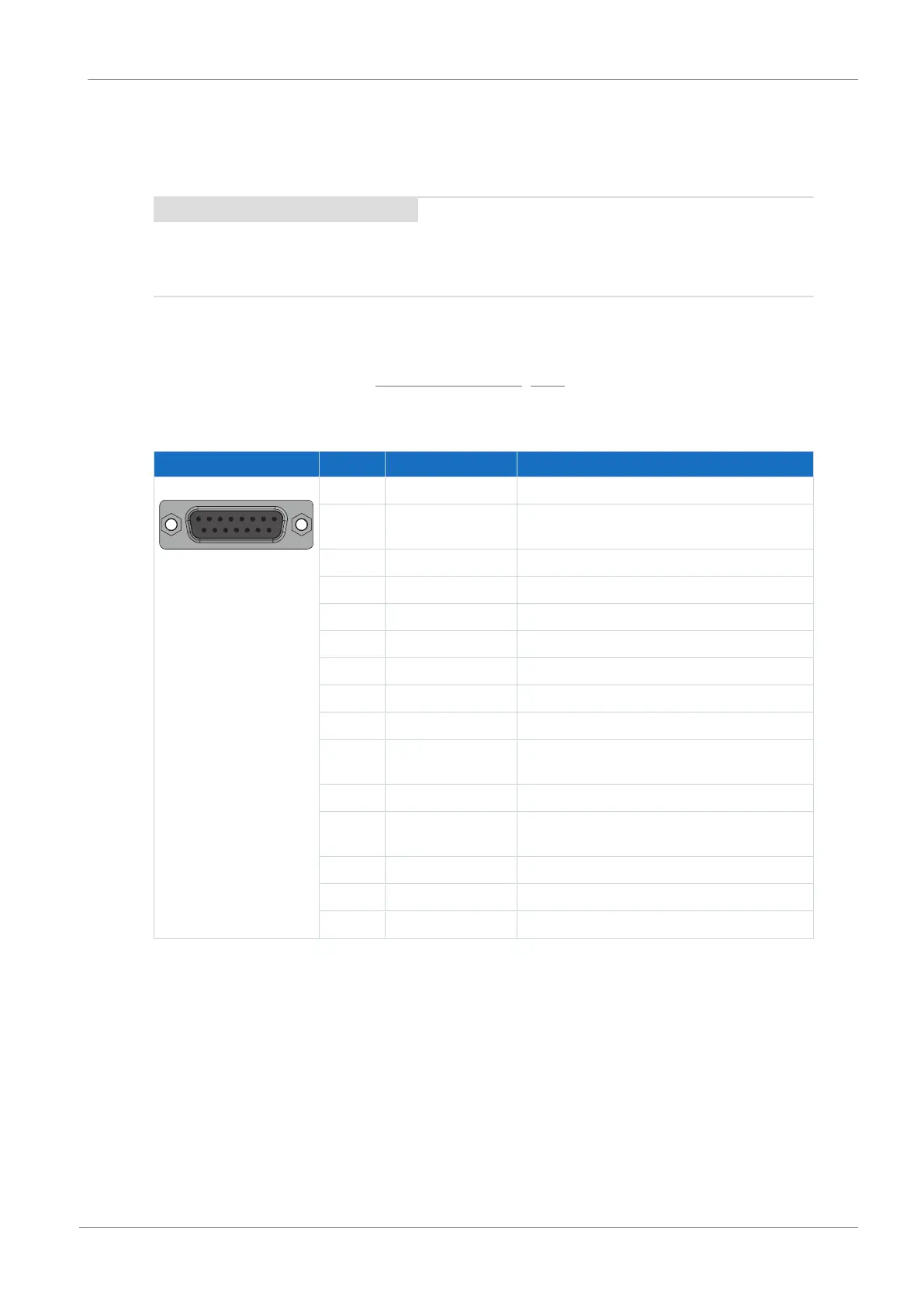
EnDat 2.1/2.2 digital encoders and SSI encoders
Socket Pin Designation Function
8|7|6|5|4|3|2|1
15|14|13|12|11|10|9
1 — —
2 GND Reference potential for encoder supply to pin
4
3 — —
4 U
2
Encoder supply
5 Data+ Differential input for DATA
6 — —
7 — —
8 Clock+ Differential input for CLOCK
9 — —
10 Sense GND Optional sensing lead for the supply voltage
for regulating the encoder supply
11 — —
12 Sense U
2
Sensing lead for the supply voltage for
regulating the encoder supply
13 Data− Inverse differential input for DATA
14 — —
15 Clock− Inverse differential input for CLOCK
Tab. 57: X4 connection description for EnDat 2.1/2.2 digital encoders and SSI encoders
 Loading...


