11 | Diagnostics STOBER
144
12/2018 | ID 442537.05
11.1.5 Fieldbus network connection
The LEDs for communication diagnostics vary depending on implemented fieldbus system or
communication module.
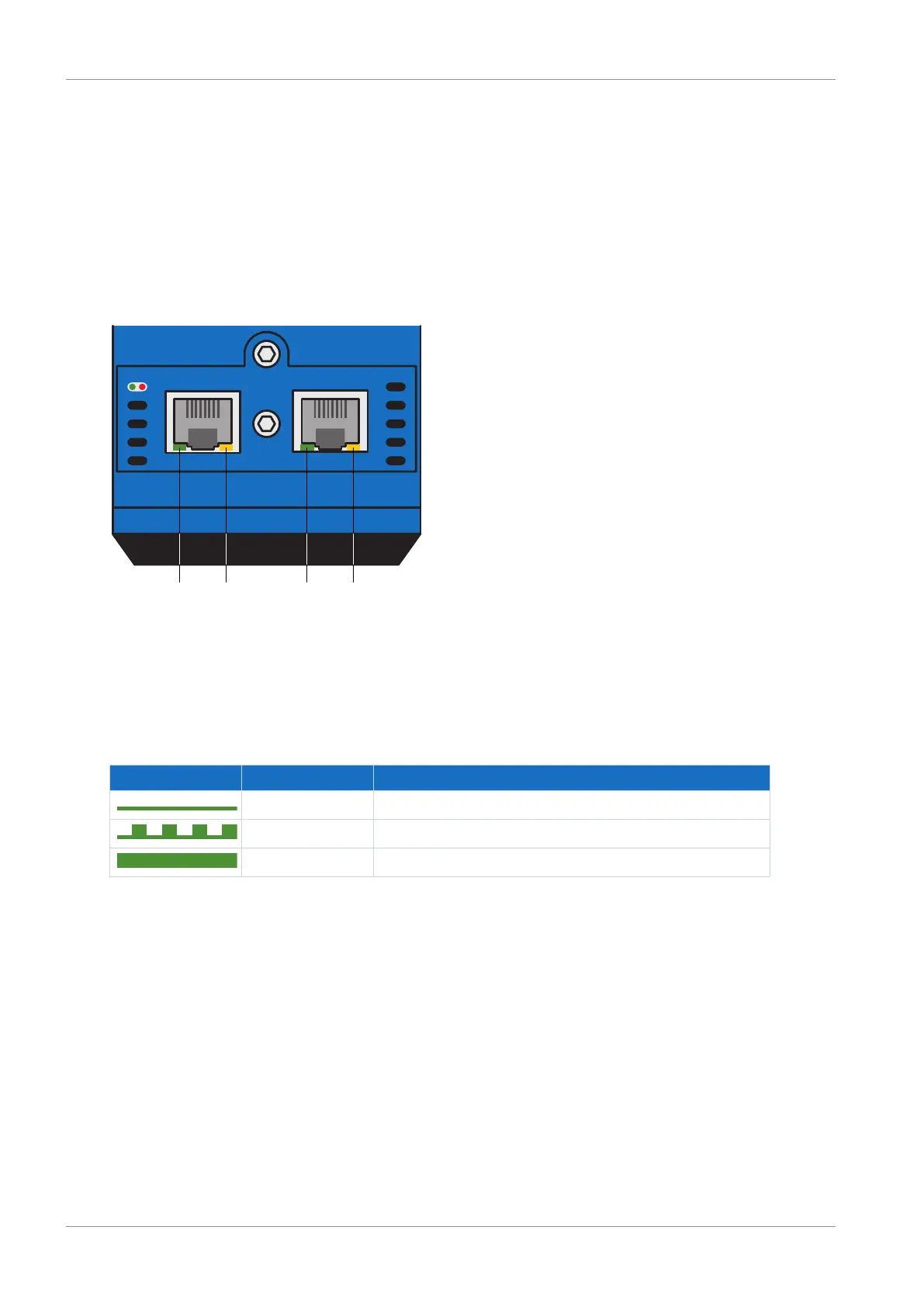
11.1.5.1 EtherCAT network connection
The LEDs LA
EC
IN and LA
EC
OUT at X200 and X201 on the top of the device display the state of
the network connection.
X200
21 43
LA LA
X201
OUTINEC EC
Err-Run
Fig.33: LEDs for the state of the EtherCAT network connection
1 Green: LA
EC
IN at X200
2 Yellow: No function
3 Green: LA
EC
OUT at X201
4 Yellow: No function
Green LED Behavior Description
Off No network connection
Flashing Active data exchange with other EtherCAT nodes
On Network connection exists
Tab. 156: Meaning of the green LEDs (LA)

 Loading...


