8 | Connection STOBER
76
12/2018 | ID 442537.05
8.4.3 X1: Enable and relay 1
You enable the power unit of the drive controller using the enable signal. The function of relay 1
can be parameterized using parameter F75.
Technical data
Observe the technical data for X1; see the chapter Enable and relay [}28].
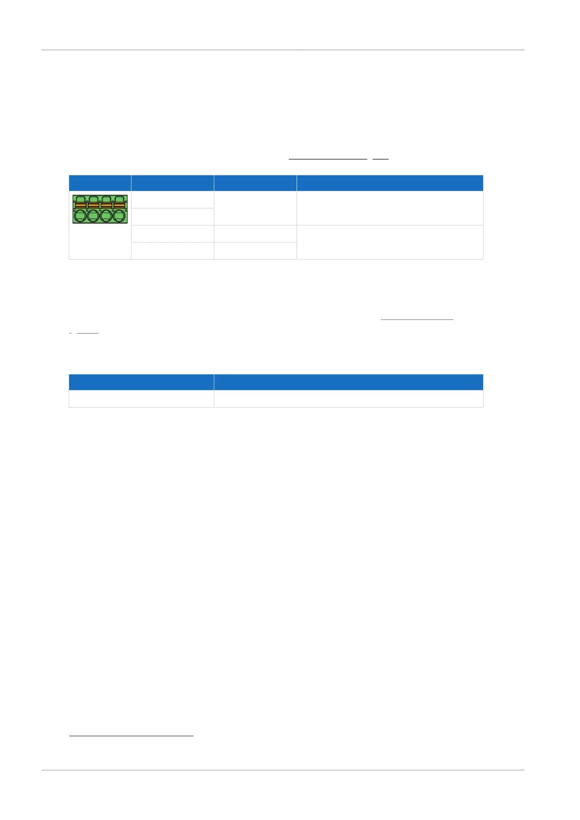
Terminal Pin Designation Function
1 | 2 | 3 | 4
1 NO contact Relay 1;
recommended fuse protection: max. 1AT
5
2
3 GND Enable
4 Input
Tab. 52: X1 connection description
Connecting wiring
For connecting wiring, observe the terminal specifications in the chapter FMC 1,5 -ST-3,5
[}151].
Cable requirements
Feature All sizes
Max. cable length 30m
Tab. 53: Cable length [m]
5
For fuse protection, use a 1A fuse (time delay) upstream of relay 1. For UL-compliant use, be sure that
the fuse meets certification requirements for DC voltage in accordance with UL 248.
 Loading...


