5 | Technical data STOBER
28
12/2018 | ID 442537.05
5.1.6.6 Enable and relay
You enable the power unit of the drive controller using the enable signal. The function of relay 1
can be parameterized using parameter F75.
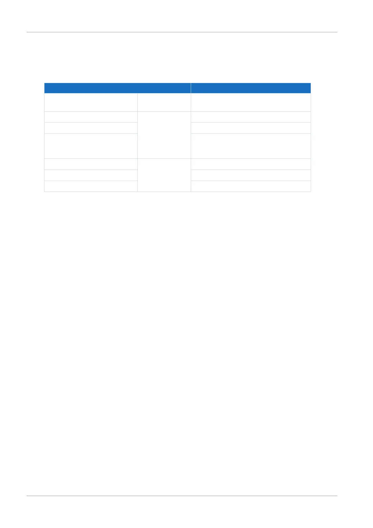
Electrical data All types
Internal device update rate Cycle time parameterized in A150 of the
application: t
min
= 1ms
U
2max
Relay 1 30V
I
2max
1.0A
Life span Mechanical min. 5,000,000 switching cycles;
at 24V
DC
/1A (ohm. load): 300,000 switching
cycles
High level Enable 12 – 30V
DC
Low level 0 – 8V
DC
I
1max
16mA
Tab. 28: X1 electrical data

 Loading...

