8 | Connection STOBER
98
12/2018 | ID 442537.05
Top of the device:
ü
You have a system circuit diagram describing the connection of the drive controller.
1. Connect the power supply to terminal X10.
2. Optional: Connect the 24V
DC
power supply for the control electronics to terminal X11.
3. Connect terminals X14 and X15 according to your safety configuration and, optionally,
connect the plausibility encoder to X50.
4. Optional: In order to use the IGB Motion Bus function, connect additional drive controllers to
an IGB network via sockets X3A and X3B.
5. Optional: Connect the EtherCAT, CANopen or PROFINET fieldbuses to sockets X200 and
X201 via the EC6, CA6 or PN6 modules.
Wiring examples can be found in the chapter Wiring examples [}158].
8.5 Communication module
The connection descriptions of the optional communication modules can be found in the
following chapters.
8.5.1 EC6 – EtherCAT
For the EtherCAT connection, you need the optional EC6 accessory part.
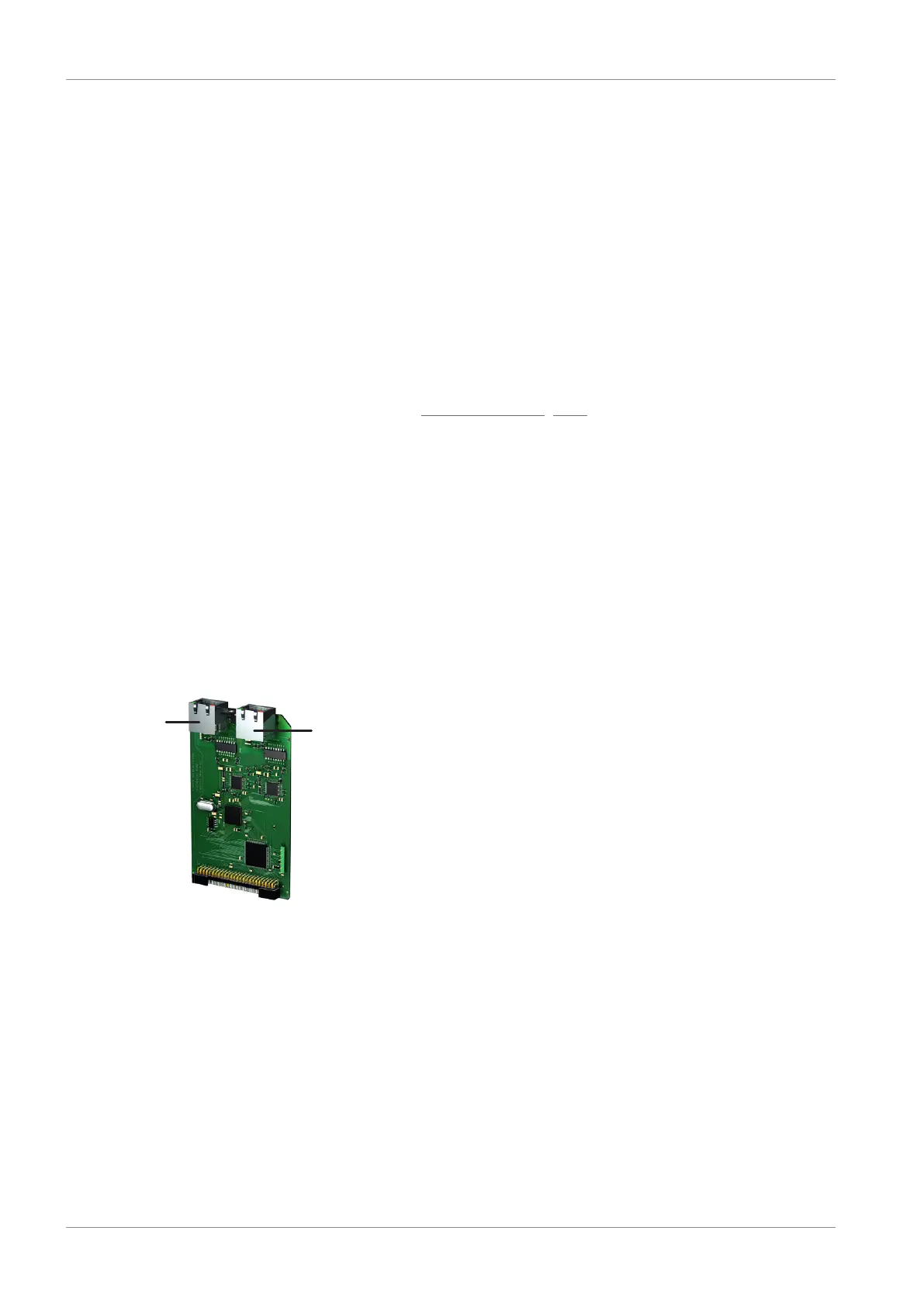
8.5.1.1 Overview
Fig.18: Connection overview for the EC6 communication module
1 X200: EtherCAT In
2 X201: EtherCAT Out
 Loading...


