STOBER 8 | Connection
12/2018 | ID 442537.05
83
8.4.9 X7: Brake 2 – Supply (SE6 option)
X7 serves as the brake supply for brake 2. The X7 connection is part of the SE6 safety module.
Electrical data All types
U
1
24 V
DC
, +20%
I
1max
8A, UL: 4A
Tab. 66: Electrical data for the brake supply
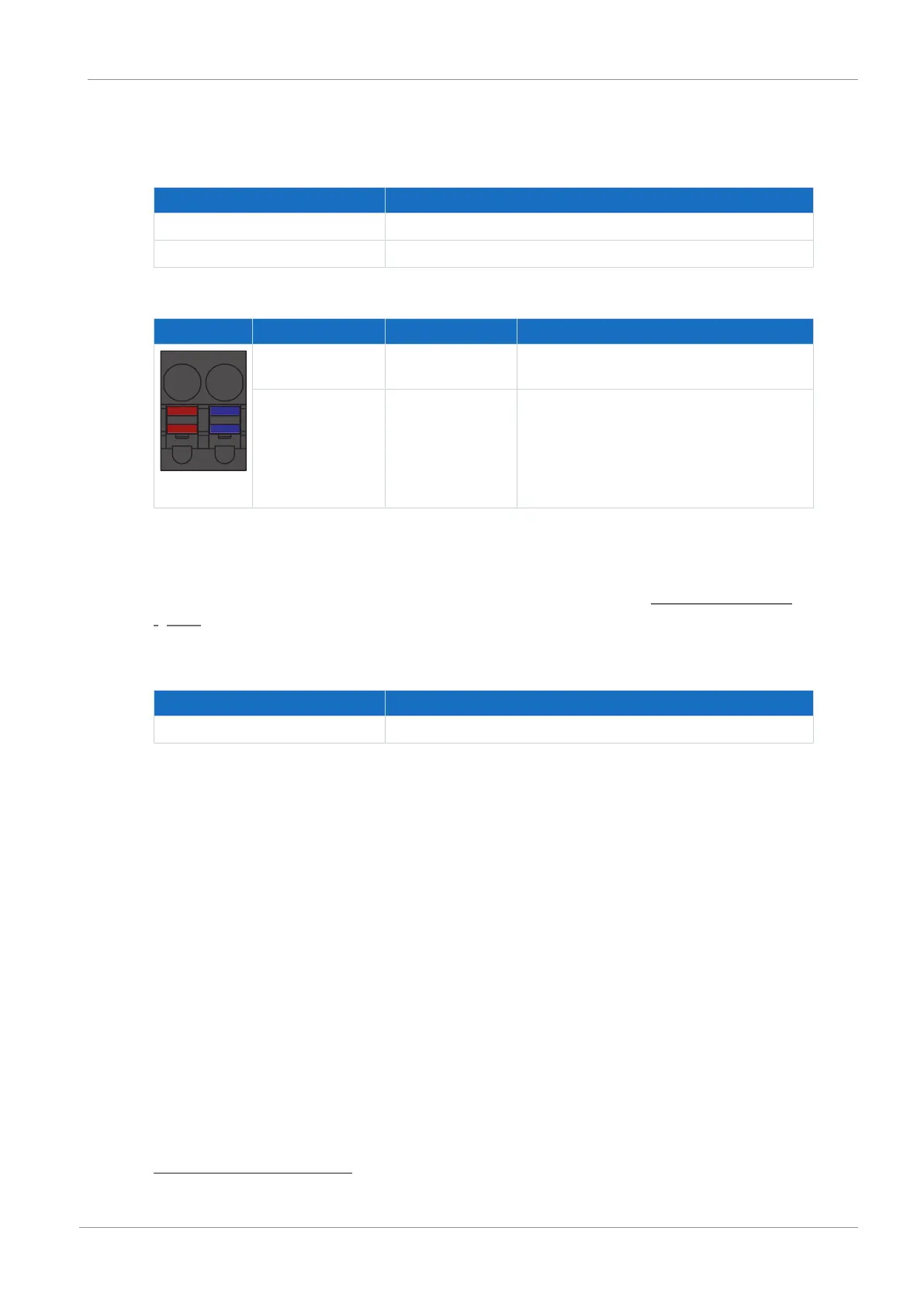
Terminal Pin Designation Function
1 | 2
1 + 24V
DC
supply for the brakes at X5 and X8;
recommended fuse protection: max. 8AT
7
2 − Reference potential for supply voltage of the
brakes
Tab. 67: X7 connection description
Connecting wiring
For connecting wiring, observe the terminal specifications in the chapter BFL 5.08HC 180 SN
[}153].
Cable requirements
Feature All sizes
Max. cable length 30m
Tab. 68: Cable length [m]
7
For UL-compliance, use of a 4A fuse (time delay) is required. Note that the fuse meets certification re-
quirements for the relevant DC voltage in accordance with UL 248.
 Loading...


