13 | Appendix STOBER
160
12/2018 | ID 442537.05
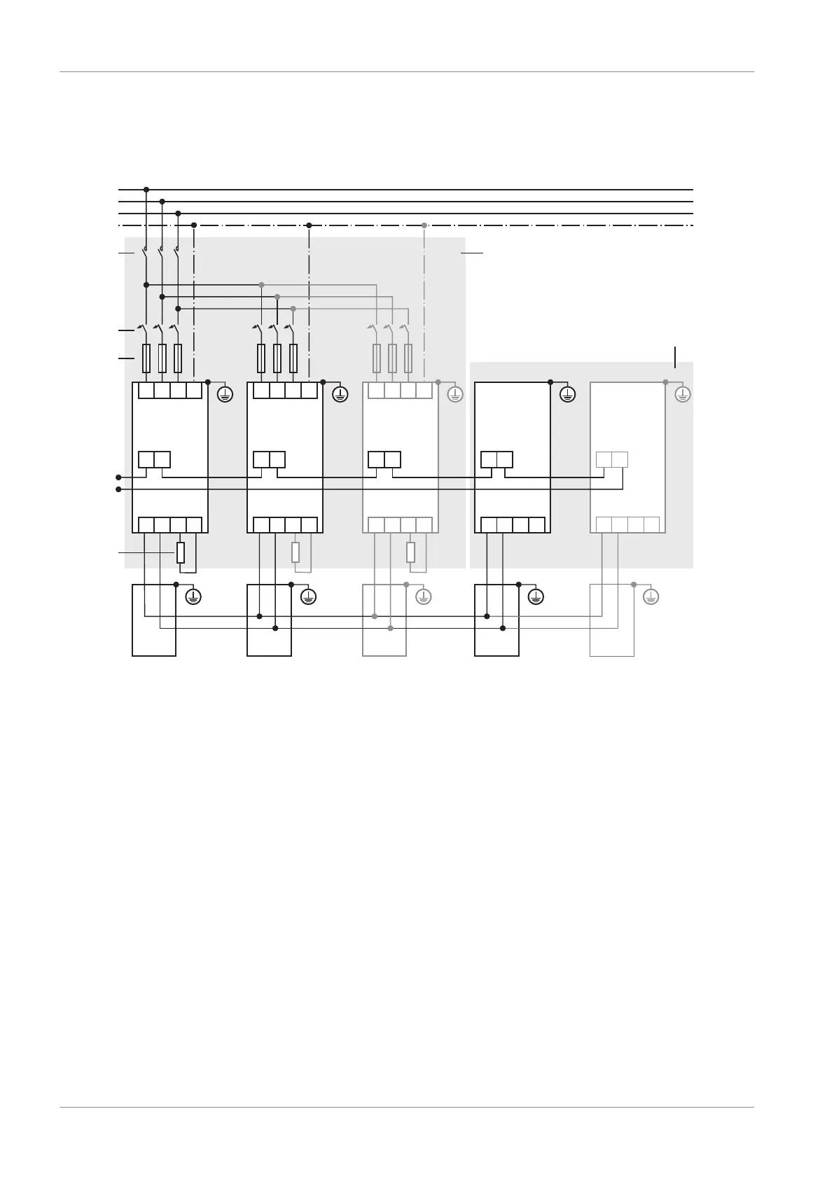
13.2.3 Parallel connection
The following graphic shows the basic connection of multiple SD6 drive controllers based on a
DC link connection with DL6A Quick DC-Link.
SD6 SD6
X10
X1
X30
R+ R-
1 2
L1
L2
L3
PE
D- D+
DL6A
DL6A
DL6A DL6A
X1
1 2
X1
1 2
X10 X10
SD6 SD6 SD6
X30 X30 X30 X30
L3
PE
L1 L2
DL6A
L3
PE
L1 L2
L3
PE
L1 L2
X1
1 2
X1
1 2
R+ R-D- D+ R+ R-D- D+ R+ R-D- D+R+ R-D- D+
1
3
4
5
6
7
2
Fig.37: Wiring example with Quick DC-Link
1 Group 1
2 Group 2
3 Grid contactor
4 Miniature circuit breaker
5 Short-circuit protection
6 Relay 1: Must be integrated into the controller; note the parameterization of the relay in F75
7 Braking resistor: Dimension the braking resistor in accordance with the Quick DC-Link braking
power and the technical data of the drive controller
 Loading...


