11 | Diagnostics STOBER
140
12/2018 | ID 442537.05
11.1.2 Service network connection
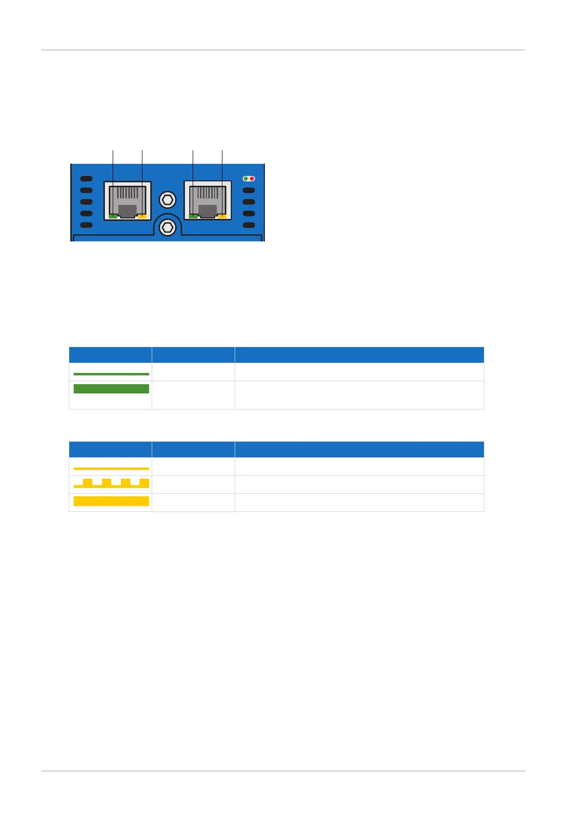
The LEDs at X3A and X3B on the top of the device indicate the state of the service network
connection.
Fig.29: LEDS for the state of the service network connection on the top of the SD6
1 LINK at X3A
2 ACTIVITY at X3A
3 LINK at X3B
4 ACTIVITY at X3B
Green LED Behavior Description
Off Physical connection not available
On Physical connection to the network is available and link is set
up
Tab. 148: Meaning of the green LED (LINK)
Yellow LED Behavior Description
Off Physical connection not available
Flashing Individual data packets are sent or received
On Continuous data communication
Tab. 149: Meaning of the yellow LED (ACTIVITY)

 Loading...

