13 | Appendix STOBER
150
12/2018 | ID 442537.05
13 Appendix
13.1 Terminal specifications
Relevant information for projecting the connecting wiring can be taken from the following
chapters.
DIN EN 60204-1 contains basic recommendations that should be taken into account when
selecting conductors. The chapter "Conductors and cables" provides specifications for the
maximum current carrying capacity of conductors based on the way they are laid as well as tips
for derating, for example in the case of increased surrounding temperatures or lines with
multiple loaded individual conductors.
WARNING!
Risk of personal injury or material damage due to electric shock and thermal overload!
▪ Prepare the conductor ends according to the terminal specifications.
▪ In the case of pre-made cables and conductors, check the conductor ends and adjust them
if necessary.
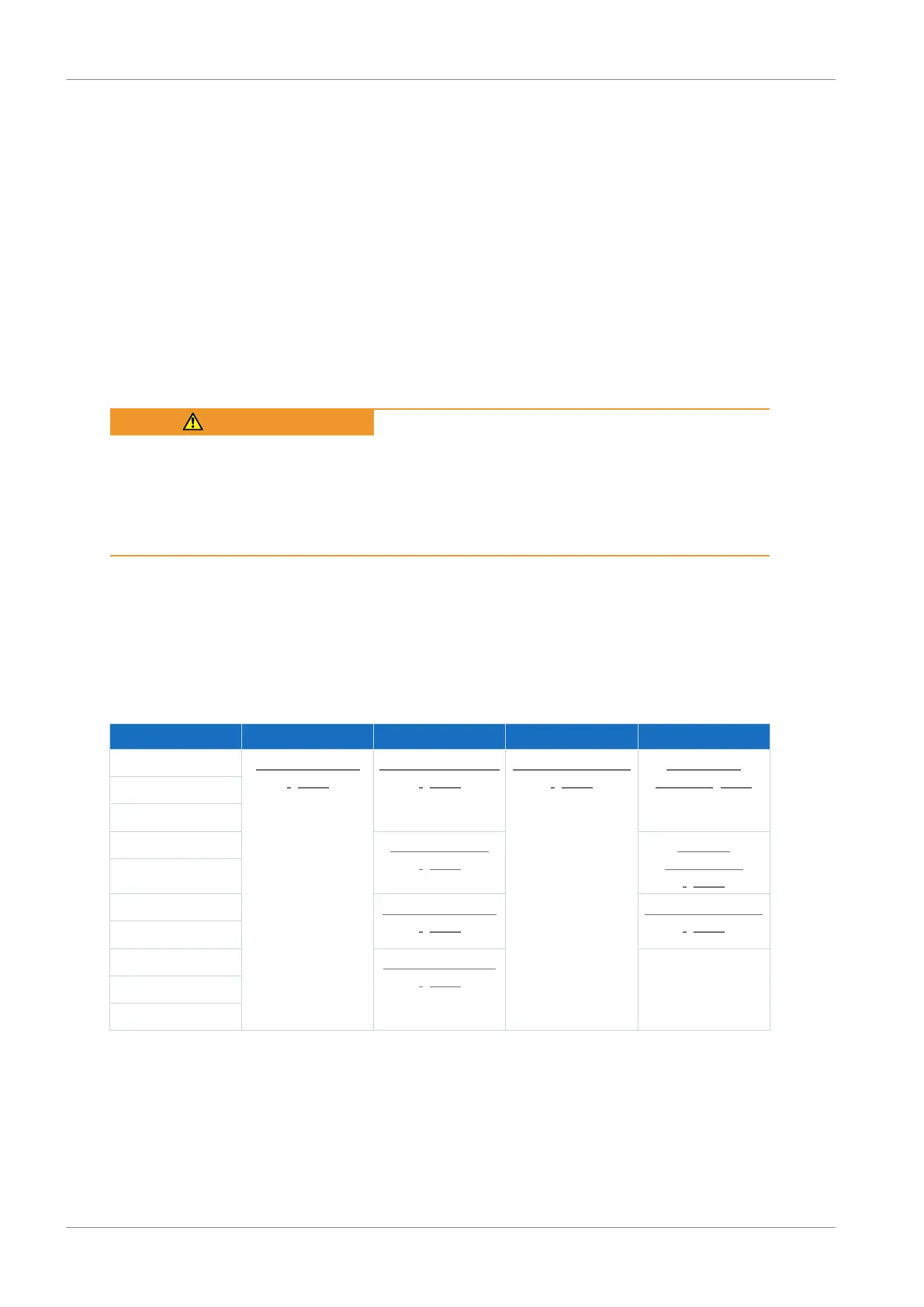
13.1.1 Overview
The following tables clarify which specifications must be observed for which connections
depending on the type of drive controller or accessory.
Drive controller
Type X1 X10, X20 X11 X30
SD6A02 FMC 1,5 -ST-3,5
[}151]
GFKC 2,5 -ST-7,62
[}154]
BLDF 5.08 180 SN
[}153]
GFKIC 2.5 -
ST-7.62 [}155]
SD6A04
SD6A06
SD6A14 SPC 5 -ST-7,62
[}155]
ISPC 5 -
STGCL-7,62
[}156]
SD6A16
SD6A24 SPC 16 -ST-10,16
[}156]
ISPC 16 -ST-10,16
[}157]
SD6A26
SD6A34 MKDSP 25 -15,00
[}157]
—
SD6A36
SD6A38
Tab. 159: Terminal specifications for the base device
 Loading...


