8 | Connection STOBER
100
12/2018 | ID 442537.05
8.5.2 CA6 – CANopen
The optional CA6 accessory part is available for the CANopen connection.
8.5.2.1 Overview
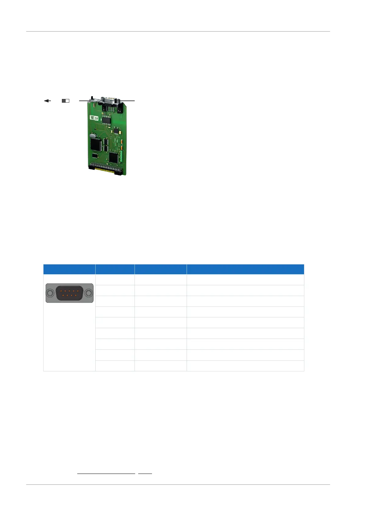
Fig.19: Connection overview for the CA6 communication module
1 Terminating resistor; must be activated at the last networked drive controller (slider to "ON")
2 X200: CANopen
8.5.2.2 X200: CANopen
The CA6 communication module provides a 9-pole D-sub connector for connecting the drive
controllers to each other.
Connector Pin Designation Function
1 | 2 | 3 | 4 | 5
6 | 7 | 8 | 9
1 — —
2 CAN-L CAN low wire
3 GND Reference ground
4 — —
5 — —
6 — CAN high wire
7 CAN-H —
8 — —
9 — —
Tab. 97: X200 connection description
Cable requirements
In order to ensure error-free operation—especially at high transmission rates—we recommend
using bus wires that meet the requirements listed in ISO 11898-2, such as the following:
§ Characteristic impedance: 95 – 140Ω
§ Maximum operating capacitance: 60nF/km
§ Conductor resistance: 70mΩ/m
Detailed information about the fieldbus connection can be found in the corresponding manual,
see chapter Detailed information [}161].
 Loading...


