STOBER 8 | Connection
12/2018 | ID 442537.05
99
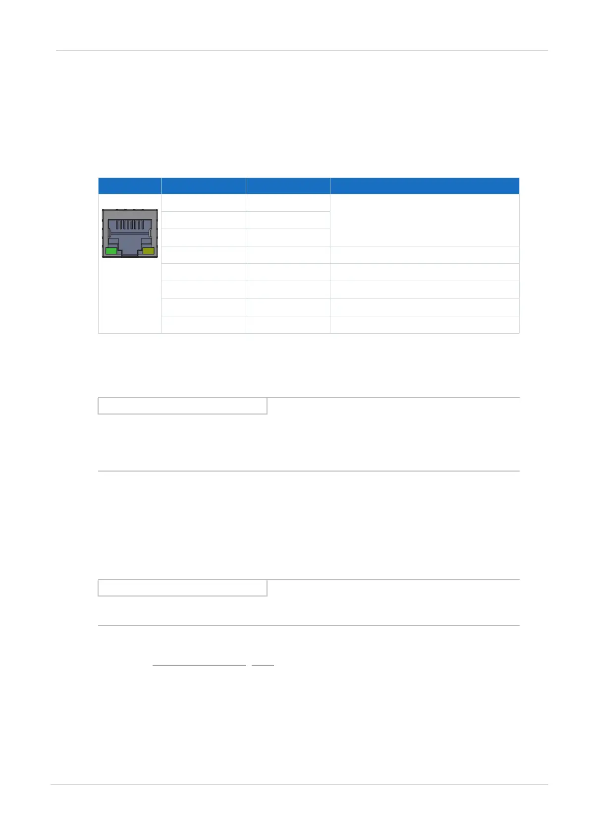
8.5.1.2 X200, X201: EtherCAT
The drive controllers have both RJ-45 sockets X200 and X201. The sockets are located on top
of the device. The associated pin assignment and color coding correspond to the EIA/TIA-
T568B standard.
X200 is to be connected as an input with the cable coming from the EtherCAT master. X201 is
to be connected as an output with any subsequent EtherCAT nodes.
Socket Pin Designation Function
1|2| ... |7|8 1 Tx+ Communication
2 Tx−
3 Rx+
4 — —
5 — —
6 Rx− Communication
7 — —
8 — —
Tab. 96: X200 and X201 connection description
Cable requirements
Information
To ensure proper functionality, we recommend using cables from STOBER that are matched to
the complete system. In case of use of unsuitable connection cables, we reserve the right to
reject claims under the warranty.
STOBER provides ready-made cables for the EtherCAT connection. It is also possible to use
cables with the following specification:
Ethernet patch cables or crossover cables meeting the CAT 5e quality level are the ideal
cables. The Fast Ethernet technology allows a maximum cable length of 100m between two
nodes.
Information
Ensure that you only use shielded cables with an SF/FTP, S/FTP or SF/UTP design.
Detailed information about the fieldbus connection can be found in the corresponding manual,
see chapter Detailed information [}161].
 Loading...


