STOBER 8 | Connection
12/2018 | ID 442537.05
121
8.6.3 IO6
8.6.3.1 Overview
2
9
11
10
12
13
15
14
16
X101
18
17
19
1
1
3
2
4
5
7
6
8
X100
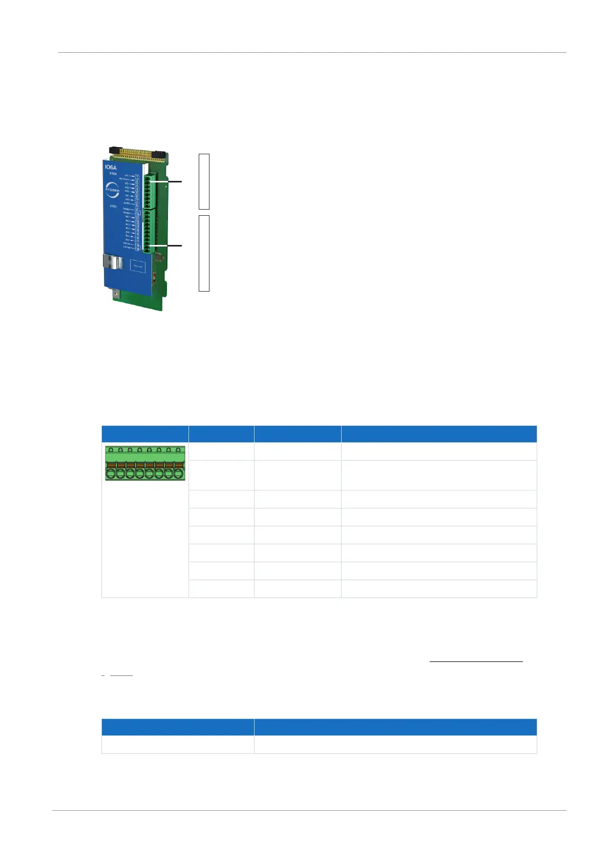
Fig.23: Connection overview for the IO6 terminal module
1 X100: AE1 – AE2, AA1 – AA2
2 X101: BE1 – BE5, BA1 – BA2
8.6.3.2 X100: AE1 – AE2, AA1 – AA2
Terminal Pin Designation Function
1|2|3|4|5|6|7|8
1 AE1+ AE1+ input
2 AE1 shunt Current input; shunt connection pin 2 is to be
bridged to pin 1
3 AE1− AE1− input
4 AE2+ AE2+ input
5 AE2− AE2− input
6 AA1 AA1 output
7 AA2 AA2 output
8 AGND Reference ground
Tab. 139: X100 connection description
Connecting wiring
For connecting wiring, observe the terminal specifications in the chapter FK-MCP 1,5 -ST-3,5
[}152].
Cable requirements
Feature All sizes
Max. cable length 30m
Tab. 140: Cable length [m]
 Loading...


