8 | Connection STOBER
122
12/2018 | ID 442537.05
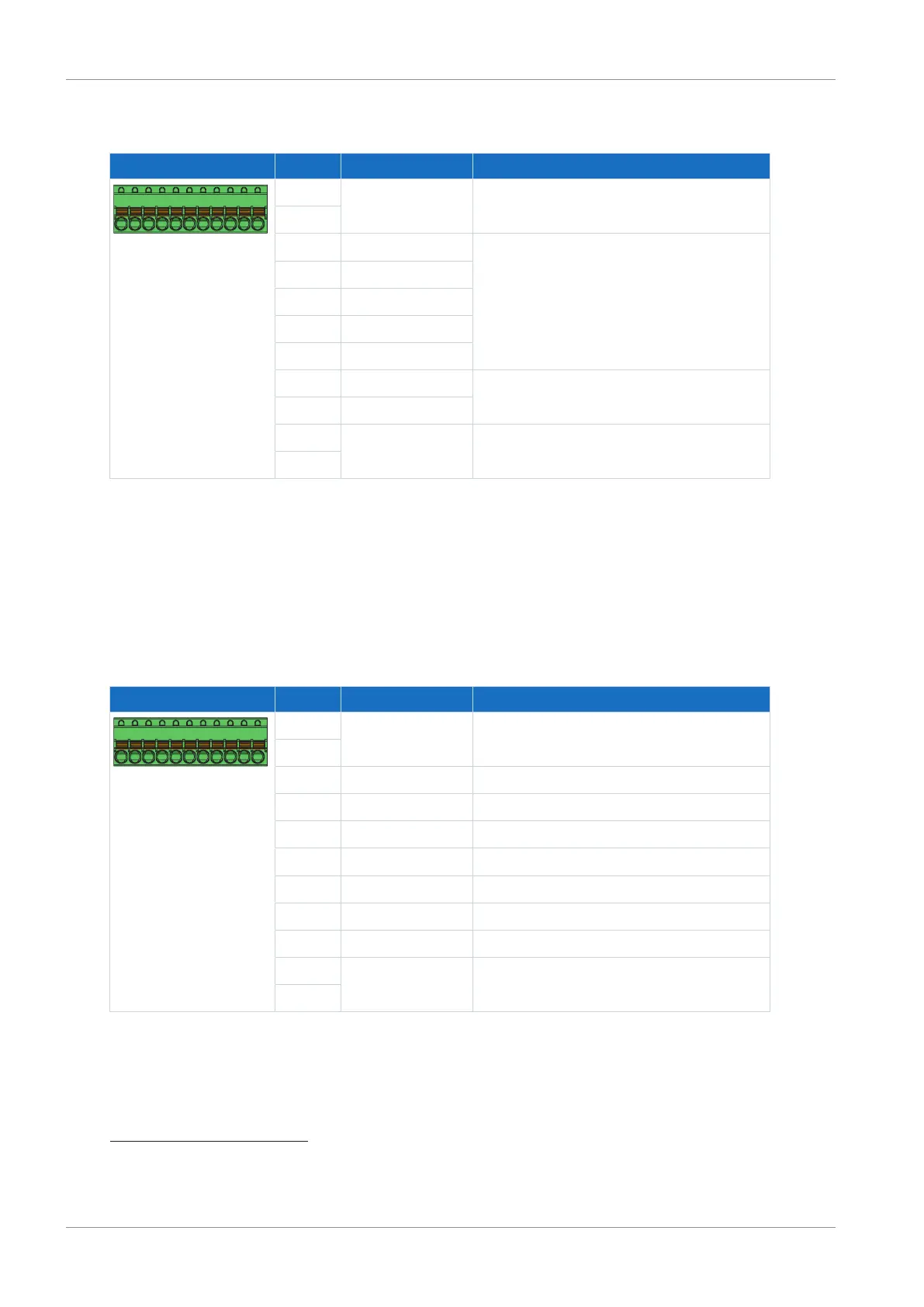
8.6.3.3 X101: BE1 – BE5, BA1 – BA2
Terminal Pin Designation Function
9|10|11| ... |17|18|19
9 DGND Reference ground, internally bridged
10
11 BE1 Binary input
12 BE2
13 BE3
14 BE4
15 BE5
16 BA1 Binary output
17 BA2
18 +24V
DC
External 24V
DC
supply; recommended fuse
protection: max. 1AT
28
19
Tab. 141: X101 connection description for binary signals
Use the binary inputs BE3 to BE5 to evaluate incremental or pulse/direction signals. For the
simulation, use the binary outputs BA1 and BA2.
Hall sensors with single-ended HTL signal levels can be connected to binary inputs BE1
through BE3 directly.
Single-ended HTL incremental encoders
Terminal Pin Designation Function
9|10|11| ... |17|18|19
9 DGND Reference ground, internally bridged
10
11 BE1 —
12 BE2 —
13 BE3 Evaluation: N channel
14 BE4 Evaluation: A channel
15 BE5 Evaluation: B channel
16 BA1 Simulation: A channel
17 BA2 Simulation: B channel
18 +24V
DC
External 24V
DC
supply; recommended fuse
protection: max. 1AT
29
19
Tab. 142: X101 connection description for single-ended HTL incremental signals
28
For the fuse protection, use a 1A fuse (time delay). For UL-compliant use, be sure that the fuse meets
certification requirements for DC voltage in accordance with UL 248.
29
For the fuse protection, use a 1A fuse (time delay). For UL-compliant use, be sure that the fuse meets
certification requirements in accordance with UL 248.
 Loading...


