STOBER 8 | Connection
12/2018 | ID 442537.05
123
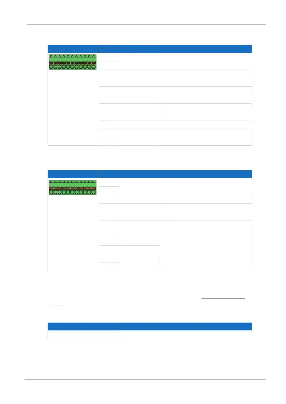
Single-ended HTL pulse train
Terminal Pin Designation Function
9|10|11| ... |17|18|19
9 DGND Reference ground, internally bridged
10
11 BE1 —
12 BE2 —
13 BE3 —
14 BE4 Evaluation: Pulse
15 BE5 Evaluation: Direction
16 BA1 Simulation: Pulse
17 BA2 Simulation: Direction
18 +24V
DC
External 24V
DC
supply; recommended fuse
protection: max. 1AT
30
19
Tab. 143: X101 connection description for single-ended HTL pulse train signals
Single-ended HTL hall sensor
Terminal Pin Designation Function
9|10|11| ... |17|18|19
9 DGND Reference ground, internally bridged
10
11 BE1 HALL A
12 BE2 HALL B
13 BE3 HALL C
14 BE4 Binary input
15 BE5
16 BA1 Binary output
17 BA2
18 +24V
DC
External 24V
DC
supply; recommended fuse
protection: max. 1AT
31
19
Tab. 144: X101 connection description for single-ended HTL hall sensor signals
Connecting wiring
For connecting wiring, observe the terminal specifications in the chapter FK-MCP 1,5 -ST-3,5
[}152].
Cable requirements
Feature All sizes
Max. cable length 30m
Tab. 145: Cable length [m]
30
For the fuse protection, use a 1A fuse (time delay). For UL-compliant use, be sure that the fuse meets
certification requirements in accordance with UL 248.
31
For the fuse protection, use a 1A fuse (time delay). For UL-compliant use, be sure that the fuse meets
certification requirements for relevant DC voltage in accordance with UL 248.
 Loading...


