STOBER 7 | Installation
12/2018 | ID 442537.05
51
7.10 Installing a rear section braking resistor
If you are using the type RB 5000 rear section braking resistor available for drive controllers of
sizes 0 to 2, you must mount this first and then build over it with the appropriate drive controller.
Information
Note that you cannot combine DL6A Quick DC-Link modules and RB 5000 rear section braking
resistors within a group.
DANGER!
Electrical voltage! Risk of fatal injury due to electric shock!
▪ Always switch off all power supply voltage before working on the devices!
▪ Note the discharge time of the DC link capacitors in the general technical data. You can
only determine the absence of voltage after this time period.
Tools and material
You will need:
§ The M5 threaded bolts included with the rear section braking resistor and the accompanying
screw and washer assemblies (screws with flat and spring washers)
§ An 8 mm hexagonal socket wrench
Requirements and installation
ü
In accordance with the drilling diagram, taking into consideration the various device
dimensions, you have made threaded holes for the threaded bolts on the mounting plate at
the mounting position.
ü
The mounting plate has been cleaned (free of oil, grease and swarf).
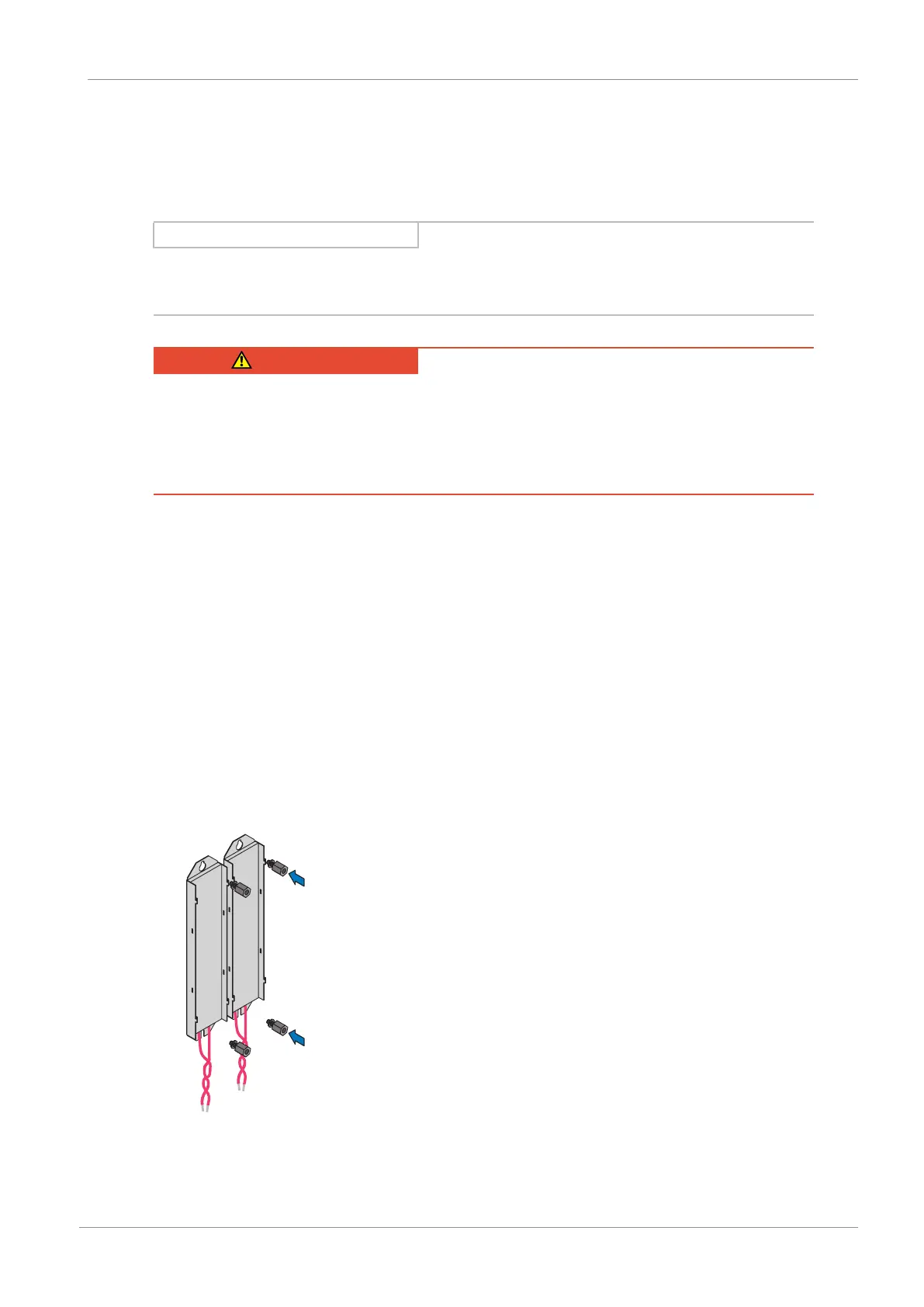
1. Fasten the rear section braking resistor to the mounting plate using the threaded bolts.
ð You have installed the rear section braking resistor. In the next step, build over it with the
appropriate drive controller.
 Loading...


