10 | Commissioning STOBER
136
12/2018 | ID 442537.05
10.3.2 Test using the operating unit of the drive controller
You have connected the SD6 drive controller along with its accessories as described and would
like to test the components in the group for correct wiring and functionality. STOBER standard
parameterization enables an initial function test if you are operating the drive controller together
with a STOBER synchronous servo motor and an EnDat encoder. In this case, the electronic
nameplate of the motor is read out when the device starts and the accompanying data is
transferred into the drive controller.
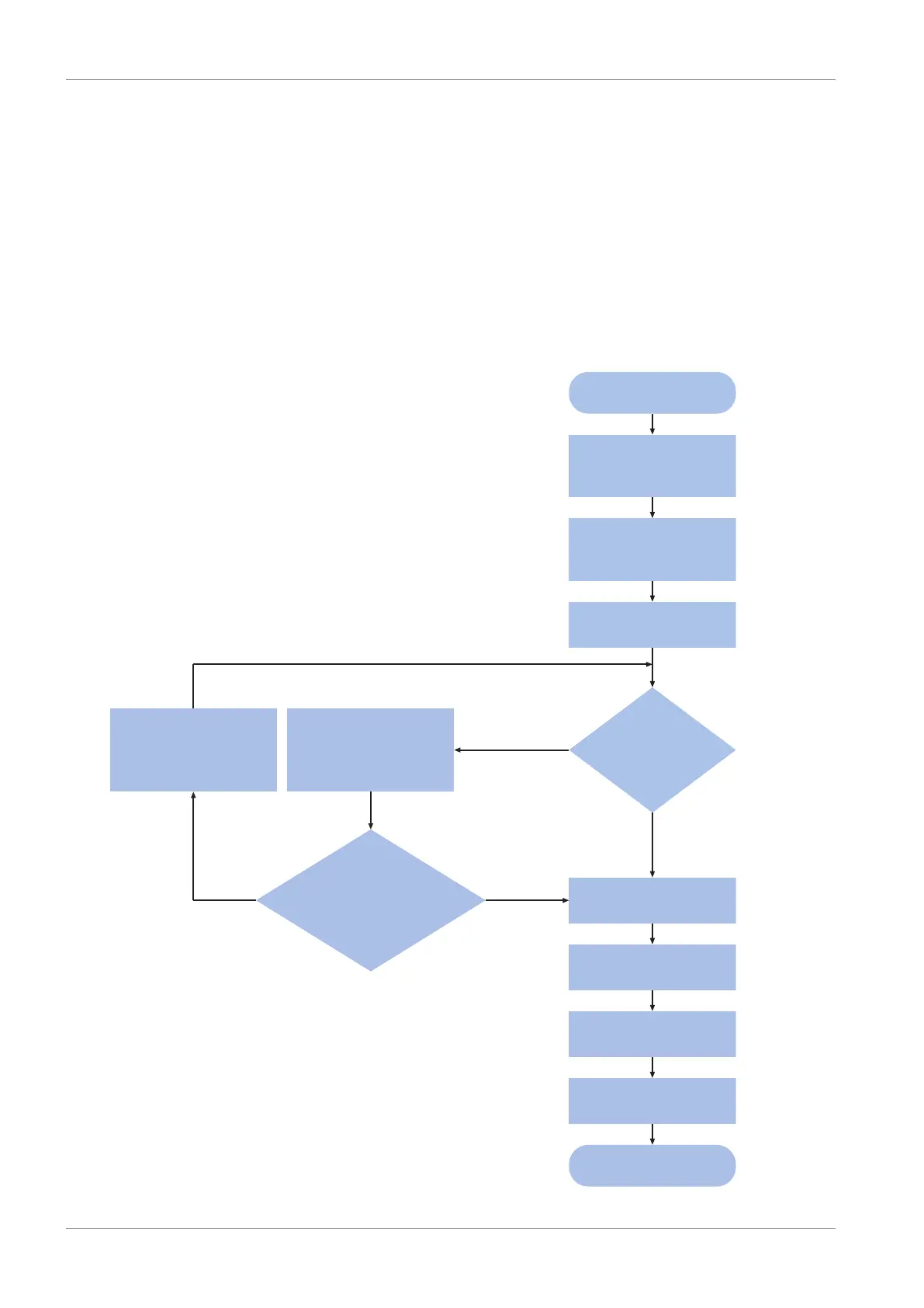
10.3.2.1 Schematic test sequence
Schematic test sequence
The following illustration shows the schematic sequence of the wiring and function test.
Remedy
causes
Activate
local operation
Ready to switch on
Enable
drive controller
Move axis
Test end
Determine
causes
(E47, E49)
Single cause:
no enable signal
for application?
(E47, E49.x)
Switch on
power grid supply
Switch on
24V supply
for drive controller
Switch on
24V supply
for brake
Test start
Yes
Switch-on disabled?
(E48)
No
YesNo
Fig.26: Schematic test sequence for wiring and function test

 Loading...

