STOBER 7 | Installation
12/2018 | ID 442537.05
41
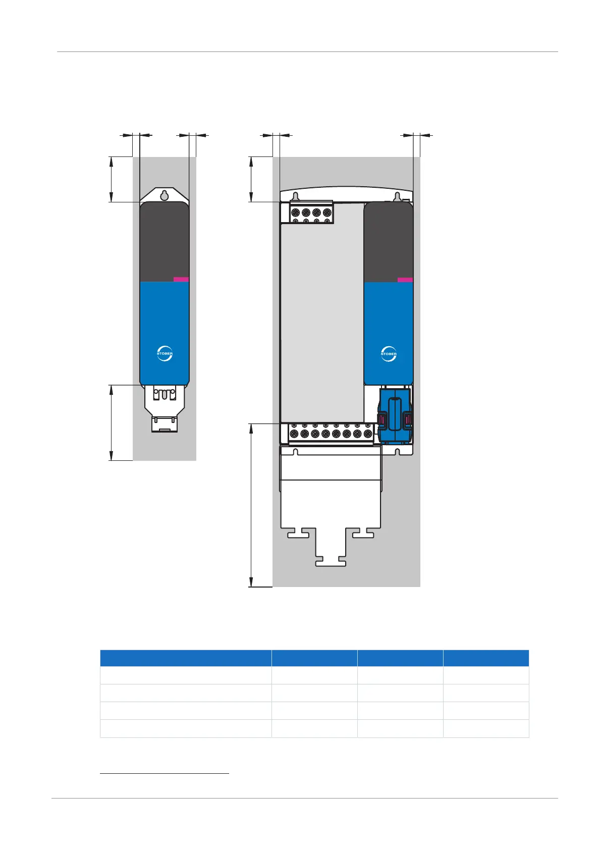
7.3 Minimum clearances
Note the minimum clearances for installation below.
Fig.7: Minimum clearances
The specified dimensions relate to the outer edges of the drive controller.
Minimum clearance A (above) B (below) C (one the side)
2
Size 0 – Size 2 100 100 5
... with EMC shroud 100 120 5
Size 3 100 100 5
... with EMC shroud 100 220 5
Tab. 44: Minimum clearances [mm]
2
Installation without Quick DC-Link module
 Loading...


