8 | Connection STOBER
84
12/2018 | ID 442537.05
8.4.10 X8: Brake 2 – Safe brake control (SE6 option)
X8 serves as the safe brake control for brake 2. The X8 connection is part of the SE6 safety
module.
Controllable brakes
Note the technical data of the brakes controllable at X8; see the chapter X8 (SE6 option) [}35].
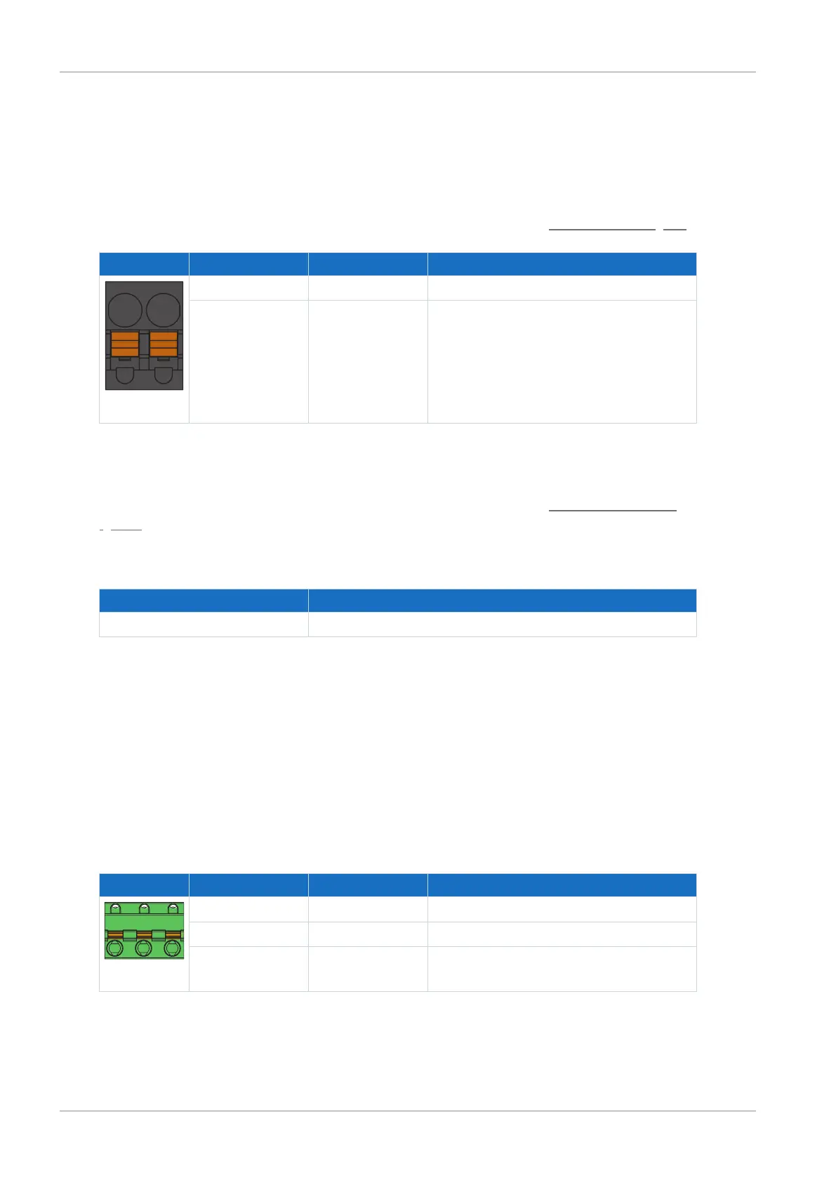
Terminal Pin Designation Function
3 | 4
3 SBC+ Output for brake control 2 +
4 SBC− Output for brake control 2 –
Tab. 69: X8 connection description
Connecting wiring
For connecting wiring, observe the terminal specifications in the chapter BFL 5.08HC 180 SN
[}153].
Cable requirements
Feature All sizes
Max. cable length 100m, shielded
Tab. 70: Cable length [m]
8.4.11 X10: 230/400V supply
Terminal X10 serves to connect the drive controller to the supply grid.
Conductor cross-sections for the power connection
When selecting the conductor cross-section, note the line fuse, the maximum permitted
conductor cross-section of terminal X10, the routing method and the surrounding temperature.
Size 0
Terminal Pin Designation Function
1 | 2 | 3
1 L1 Power supply
2 N Neutral conductor
3 PE Grounding conductor
Tab. 71: X10 connection description – Size 0, 1-phase line connection

 Loading...

