STOBER 8 | Connection
12/2018 | ID 442537.05
77
8.4.4 X2: Motor temperature sensor
Terminal X2 is provided for connecting motor temperature sensors. The following can be
connected to all SD6 drive controller device types:
§ A KTY84-130 in one winding,
§ A Pt1000 in one winding,
§ A PTC triplet or maximum two PTC triplets for multiple motor operation
Information
Note that the evaluation of the temperature sensor is always active. If operation without a
temperature sensor is permitted, the connections must be bridged on X2. Otherwise a fault is
triggered when switching on the device.
Information
STOBER recommends the use of PTC thermistors as thermal winding protection.
Motor temperature sensor wires in the resolver or EnDat cable for SDS 4000
If you replace an SDS 4000 with an SD6, the wires of the motor temperature sensor are
maintained in the previously used encoder cable. To be able to continue using the cable, you
need the RI6 terminal module, to which you can connect the cable via an AP6 interface adapter.
The adapter is available in three different designs.
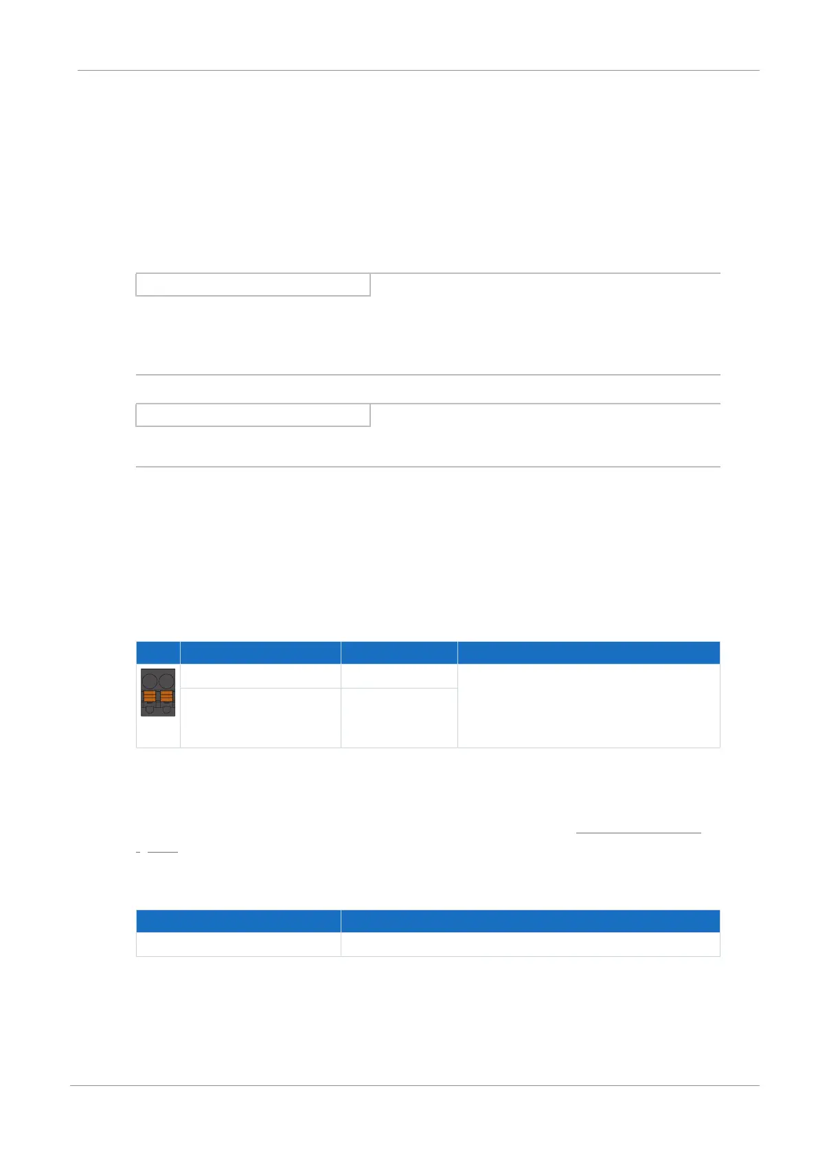
Connection description
Pin Designation Function
7 | 8
7 1TP1/1K1 PTC/Pt1000/KTY connection
8 1TP2/1K2
Tab. 54: X2 connection description
Connecting wiring
For connecting wiring, observe the terminal specifications in the chapter BFL 5.08HC 180 SN
[}153].
Cable requirements
Feature All sizes
Max. cable length 100m
Tab. 55: Cable length [m]

 Loading...


