STOBER 5 | Technical data
12/2018 | ID 442537.05
35
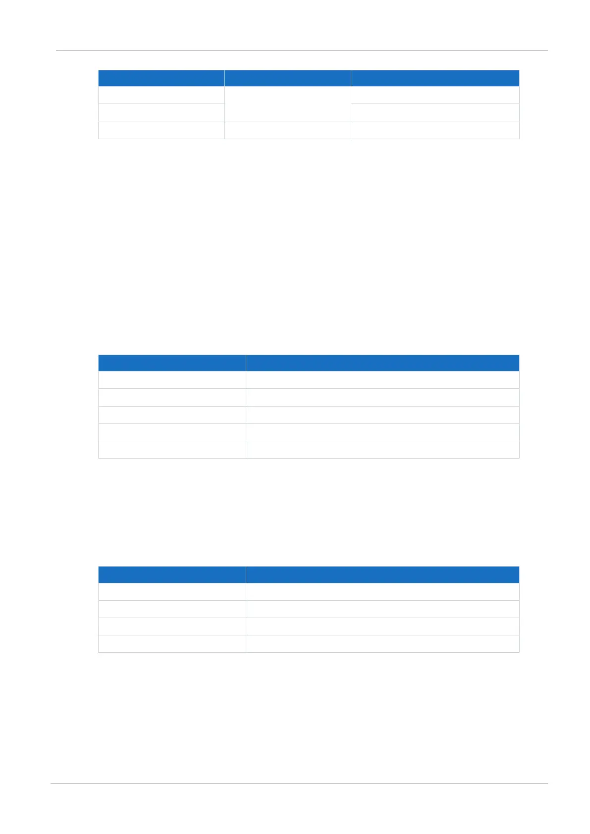
Electrical data Digital output Value
I
2max
O0 – O4 0.5A
Typical voltage drop 25mV
U
1
24V
DC
supply 20.4 – 28.8V
DC
Tab. 41: X15 electrical data – Digital outputs (SE6 option)
5.4 Controllable brakes
You can control the following brakes:
§ 24V
DC
brakes connected directly to X5
§ Brakes connected indirectly (e.g. over coupling contactor) to X5
Only in combination with SE6 safety module:
§ 24V
DC
brakes connected directly to X8
§ Brakes connected indirectly (e.g. over coupling contactor) to X8
5.4.1 X5
Electrical data Brake output
I
2max
3A
I
2min
(direct brake control) 330mA
I
2min
(indirect brake control) 20mA
f
2max
1Hz
E
2max
2.84J
Tab. 42: Electrical data of the brake output
In combination with the ST6 safety module, the brake connected to X5 is supplied over terminal
X6, in combination with the SE6 safety module over terminal X7.
5.4.2 X8 (SE6 option)
Electrical data Brake output
I
2max
3.6A / 2.5A at surrounding temperature > 45 °C
I
2min
0.5mA
f
2max
1Hz
E
2max
4.5J
Tab. 43: Electrical data of the brake output
The brake connected to X8 is supplied over terminal X7.
 Loading...


