8 | Connection STOBER
92
12/2018 | ID 442537.05
8.4.17 X30: DC link connection, braking resistor
Terminal X30 is available in sizes 0 to 2 for the DC link connection of the drive controller and for
the connection of a braking resistor.
For setting up the Quick DC-Link, note the information on project configuration in the manual for
the SD6 drive controller; see the chapter Detailed information [}161].
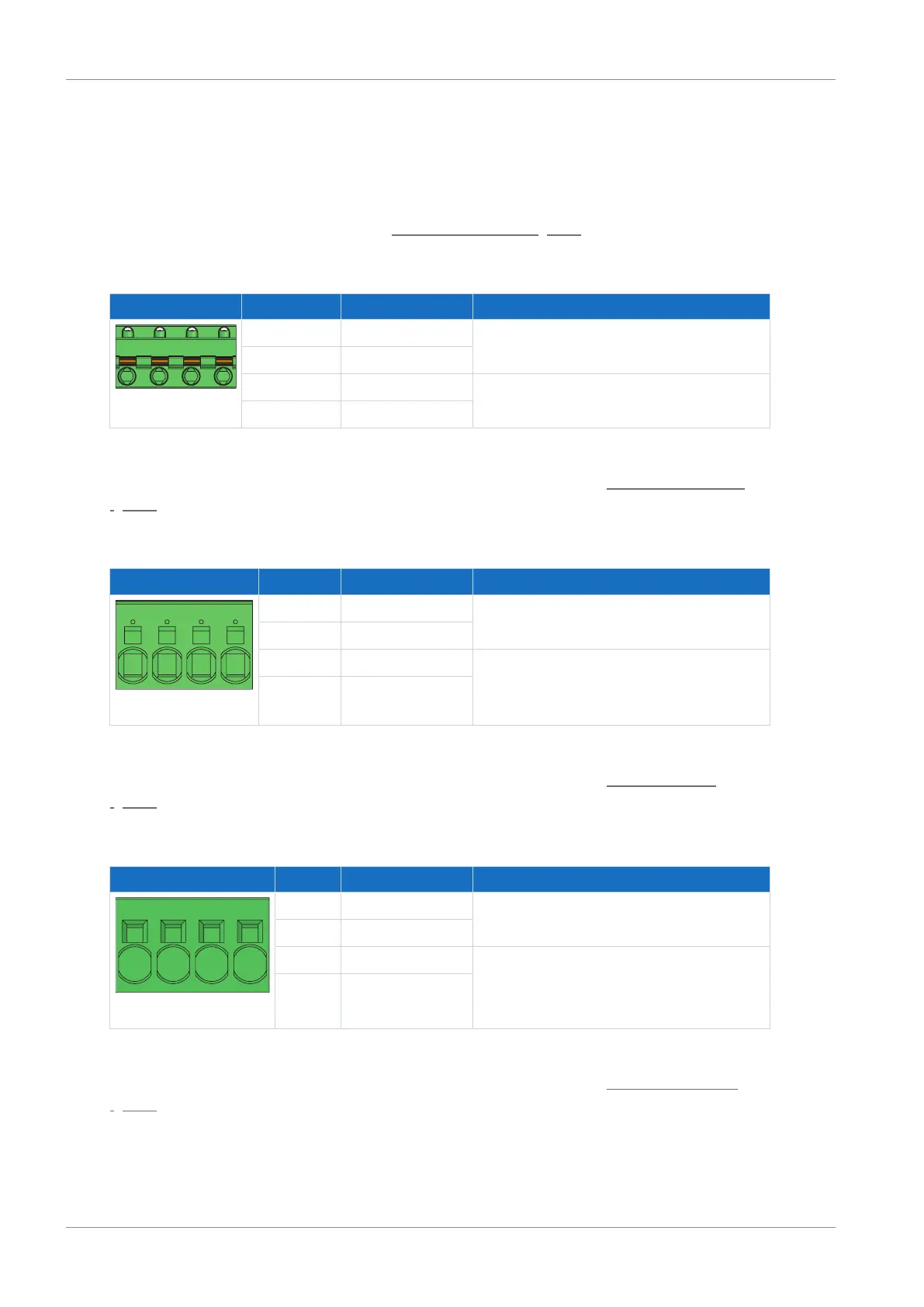
Size 0
Terminal Pin Designation Function
1 | 2 | 3 | 4
1 D− DC link connection
2 D+
3 R+ Braking resistor connection
4 R−
Tab. 90: X30 connection description – Size 0
For connecting wiring, observe the terminal specifications in the chapter GFKIC 2.5 -ST-7.62
[}155].
Size 1
Terminal Pin Designation Function
1 | 2 | 3 | 4
1 D− DC link connection
2 D+
3 R+ Braking resistor connection
4 R−
Tab. 91: X30 connection description – Size 1
For connecting wiring, observe the terminal specifications in the chapter SPC 5 -ST-7,62
[}155].
Size 2
Terminal Pin Designation Function
1 | 2 | 3 | 4
1 D− DC link connection
2 D+
3 R+ Braking resistor connection
4 R−
Tab. 92: X30 connection description – Size 2
For connecting wiring, observe the terminal specifications in the chapter ISPC 16 -ST-10,16
[}157].
Size 3
For size 3 device types, the connections for the braking resistor and Quick DC-Link are part of
terminal X20.

 Loading...

