8 | Connection STOBER
88
12/2018 | ID 442537.05
8.4.14 X14: Safety technology – Safe inputs (SE6 option)
The SE6 safety module adds the expanded safety functions to the SD6 drive controllers using
terminals X14 and X15.
Information
If you would like to use the expanded safety functionality over terminals, be sure to read the
SE6 manual; see the chapter Detailed information [}161].
Technical data
Observe the technical data of the safety options at X14 and X15; see the chapter SE6 [}34].
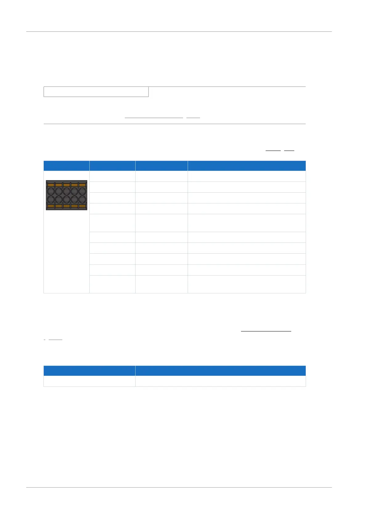
Terminal Pin Designation Function
6 | 7 | 8 | 9 | 10
1 | 2 | 3 | 4 | 5
1 I0 Safe digital input
2 I1 Safe digital input
3 I2 Safe digital input
4 I3 Safe digital input
5 GND Reference potential for digital inputs;
internally connected to pin 10
6 I4 Safe digital input
7 I5 Safe digital input
8 I6 Safe digital input
9 I7 Safe digital input
10 GND Reference potential for digital inputs;
internally connected to pin 5
Tab. 81: X14 connection description
Connecting wiring
For connecting wiring, observe the terminal specifications in the chapter DFMC 1.5 -ST-3.5
[}154].
Cable requirements
Feature All sizes
Max. cable length 100m; shielded on drive controllers of size 3
Tab. 82: Cable length [m]

 Loading...

