STOBER 5 | Technical data
12/2018 | ID 442537.05
27
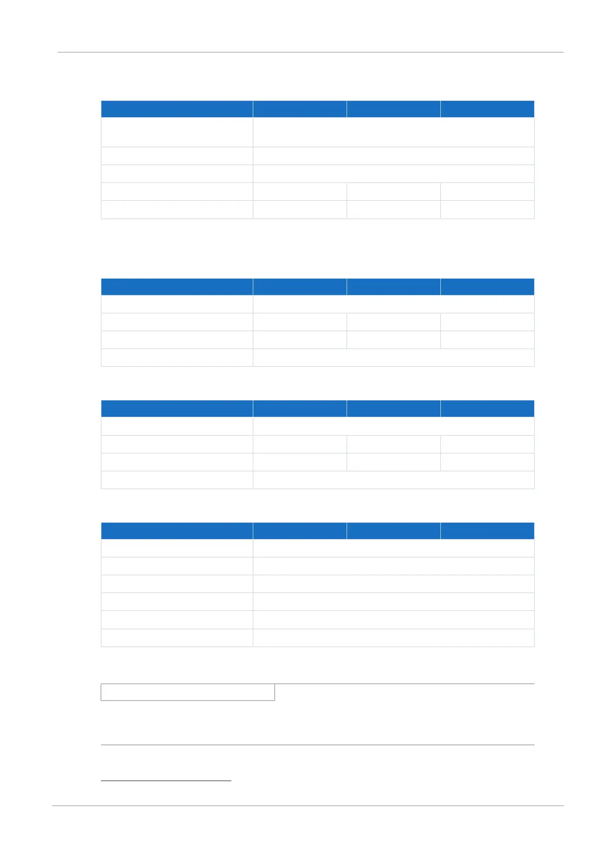
5.1.6.5 Power unit: Size 3
Electrical data SD6A34 SD6A36 SD6A38
U
1PU
3 × 400V
AC
, +32% / −50%, 50/60 Hz;
3 × 480V
AC
, +10% / −58%, 50/60Hz
f
2PU
0 – 700 Hz
U
2PU
0 – max. U
1PU
C
PU
430µF 900µF 900µF
C
maxPU
5100µF 5100µF 5100µF
Tab. 24: SD6 electrical data, size 3
Nominal currents up to +45°C (in the control cabinet)
Electrical data SD6A34 SD6A36 SD6A38
f
PWM,PU
4kHz
I
1N,PU
45.3A 76A 76A
I
2N,PU
44A 70A 85A
1
I
2maxPU
180% for 5s; 150% for 30s
Tab. 25: SD6 electrical data, size 3, for 4kHz clock frequency
Electrical data SD6A34 SD6A36 SD6A38
f
PWM,PU
8 kHz
I
1N,PU
37A 62A 76A
I
2N,PU
30A 50A 60A
I
2maxPU
250% for 2s; 200% for 5s
Tab. 26: SD6 electrical data, size 3, for 8kHz clock frequency
Electrical data SD6A34 SD6A36 SD6A38
U
onCH
780 – 800V
DC
U
offCH
740 – 760V
DC
R
intRB
30Ω (PTC resistance; 100W; max. 1kW for 1s; τ = 40s)
R
2minRB
15Ω
P
maxRB
42kW
P
effRB
19.4kW
Tab. 27: Brake chopper electrical data, size 3
Information
Be aware that the internal braking resistor is not active automatically and must be
parameterized in DriveControlSuite.
1
Specification applies to the default setting of the field weakening voltage limit: B92 = 80%.

 Loading...

