STOBER 8 | Connection
12/2018 | ID 442537.05
75
17
R
W
R
X20
12
11
X4
X1
4
2
3
1
10
X120
D
V
U
PE
D
15
13
X8
X7
16
X2
8
7
14
X5
6
5
4
3
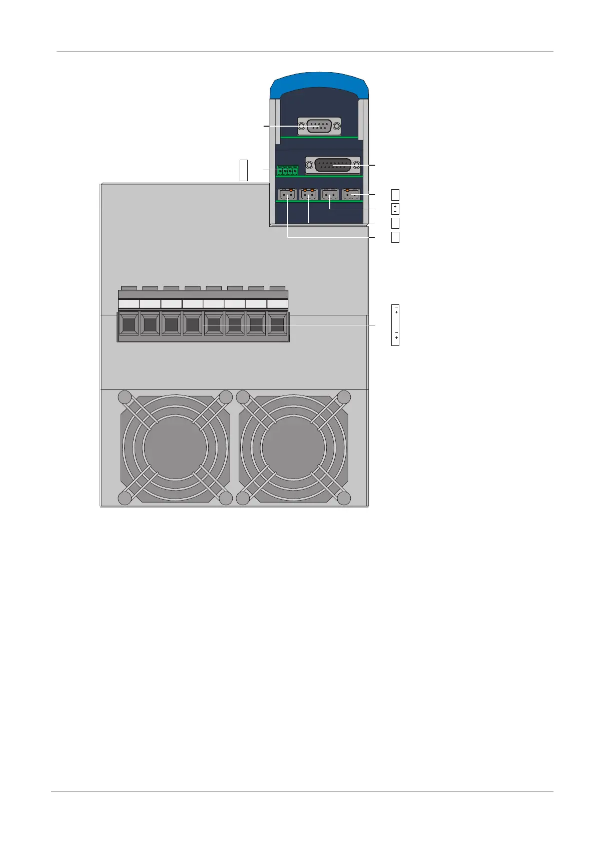
Fig.17: Connection overview of size 3 with SE6 safety module, bottom of device
10 X120: Encoder connection on optional XI6 terminal module (alternatively X120 and X140: Encoder
connections on RI6 terminal module or IO6 terminal module without encoder connection)
11 X1: Enable and relay 1
12 X4: Encoder
13 X5: Brake 1 (BD1/BD2)
14 X7: Supply for brake(s)
15 X8: Brake 2 (SBC+/−)
16 X2: Motor temperature sensor
17 X20: Motor, Quick DC-Link, braking resistor
 Loading...


