STOBER 11 | Diagnostics
12/2018 | ID 442537.05
145
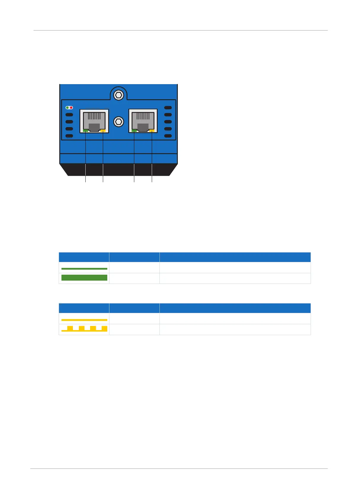
11.1.5.2 PROFINET network connection
The Act. and Link LEDs at X200 and X201 on the top of the device indicate the state of the
PROFINET network connection.
X200
21 43
Link Link
X201
Act
Act
BF-Run
Fig.34: LEDs for the state of the PROFINET network connection
1 Green: Link at X201
2 Yellow: Activity at X201
3 Green: Link at X200
4 Yellow: Activity at X200
Green LED Behavior Description
Off No network connection
On Network connection exists
Tab. 157: Meaning of the green LEDs (Link)
Yellow LED Behavior Description
Off No data exchange
Flashing Active data exchange with IO controller
Tab. 158: Meaning of the yellow LEDs (Act.)
 Loading...


