8 | Connection STOBER
80
12/2018 | ID 442537.05
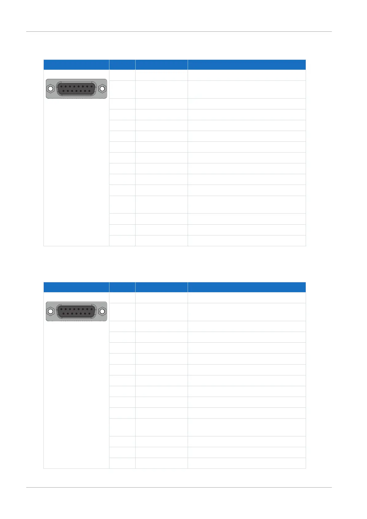
Differential HTL incremental encoders
Socket Pin Designation Function
8|7|6|5|4|3|2|1
15|14|13|12|11|10|9
1 B+ Differential input for B channel
2 GND Reference potential for encoder supply to pin
4
3 N+ Differential input for N channel
4 U
2
Encoder supply
5 — —
6 A+ Differential input for A channel
7 — —
8 — —
9 B− Inverse differential input for B channel
10 N− Inverse differential input for N channel
11 A− Inverse differential input for A channel
12 Sense U
2
Sensing lead for the supply voltage for
regulating the encoder supply
13 — —
14 — —
15 — —
Tab. 58: X4 connection description for differential HTL incremental encoders
Differential TTL incremental encoders
Socket Pin Designation Function
8|7|6|5|4|3|2|1
15|14|13|12|11|10|9
1 — —
2 GND Reference potential for encoder supply to pin
4
3 — —
4 U
2
Encoder supply
5 B+ Differential input for B channel
6 — —
7 N+ Differential input for N channel
8 A+ Differential input for A channel
9 — —
10 — —
11 — —
12 Sense U
2
Sensing lead for the supply voltage for
regulating the encoder supply
13 B− Inverse differential input for B channel
14 N− Inverse differential input for N channel
15 A− Inverse differential input for A channel
Tab. 59: X4 connection description for differential TTL incremental encoders
 Loading...


